MN-DMD20-20LBST Revision 14 3–1
Chapter 3. THEORY OF
OPERATION
3.1 Modem Hardware
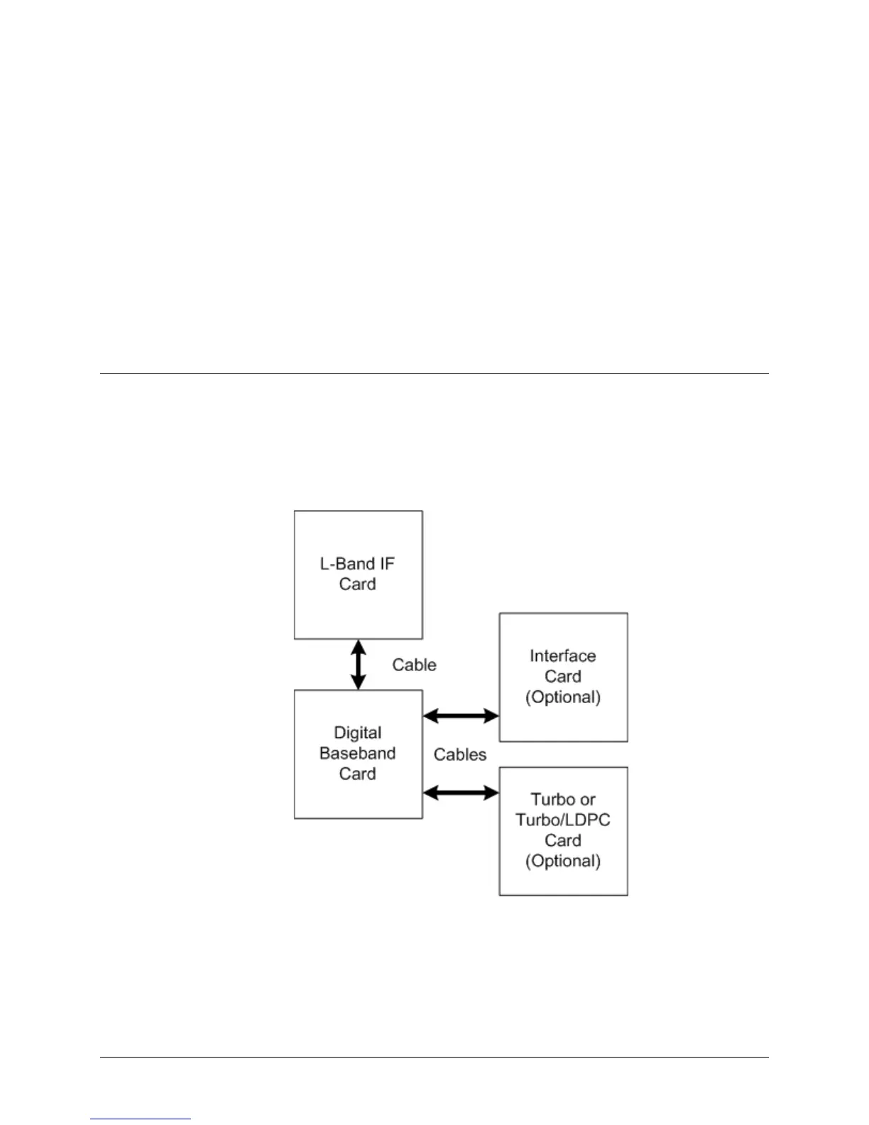
The modem is based on a two printed circuit card (minimum configuration) design with additional
optioned printed circuit cards available for additional features. The minimum configuration
consists of an L-Band/IF Assembly and a Digital Baseband Assembly. The optional printed circuit
cards include a Turbo Codec printed circuit card and one of several types of Interface printed
circuit card (refer to Appendix A). A block diagram of the Modem is shown in Figure 3-1.
Figure 3-1 Block Diagram


 To Next Page