DMD20/20LBST Universal Satellite Modem Theory of Operation
MN-DMD20-20LBST Revision 14 3–20
In Pass Thru Mode, there is no formatting or deformatting of the input data in the buffer, and it is
transmitted on a first-in first-out basis. In band data entering the remote port is inserted into the
user data stream. The in-band data is received and passed on to the user without any
deformatting or depacketizing involved. The maximum in band rate supported is 115200bps.
The Asynchronous Data Interface (J17) is a 9-Pin Female “D” Connector. The data interface is
either RS232 or RS485 via a front panel selection. Refer to Table 5-7 for pinouts.
3.14.1 SCC Framing Structure
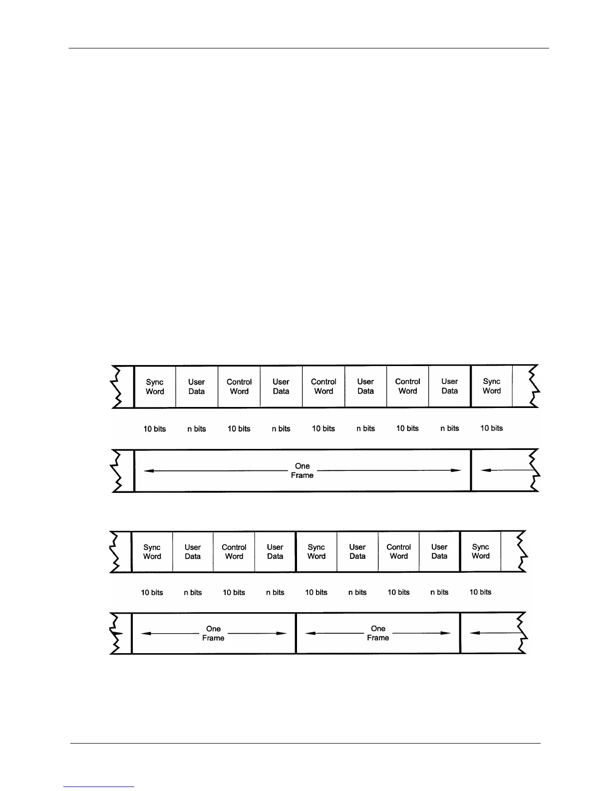
Each SCC frame consists of the following:
• A 10-bit synchronization pattern called the Synchronizing Word.
• Multiple variable length slots filled with user data.
• Multiple 10-bit control words that contains eight bits of in-band data (the extra two bits are
for the async start/stop).
The number of user data slots and control words per frame is selected by the SCC Control Ratio
Parameter. This can be any value from 1 to 1 through 1 to 7. A higher ratio allows a lower
overhead rate but since there are less Sync Words, there is a higher acquisition time.
The following examples show a control ratio of 1 to 3 and 1 to 1. Example 1 shows three Control
Words for every Synchronizing Word, and Example 2 shows one Control Word for every
Synchronizing Word.
1 to 3 Control Ratio
1 to 1 Control Ratio
The Control Ratio of the receiving units must match the Control Ratio of the transmitting unit.


 To Next Page