DMD20/20LBST Universal Satellite Modem Theory of Operation
MN-DMD20-20LBST Revision 14 3–2
3.1.1 L-Band/IF Printed Circuit Card
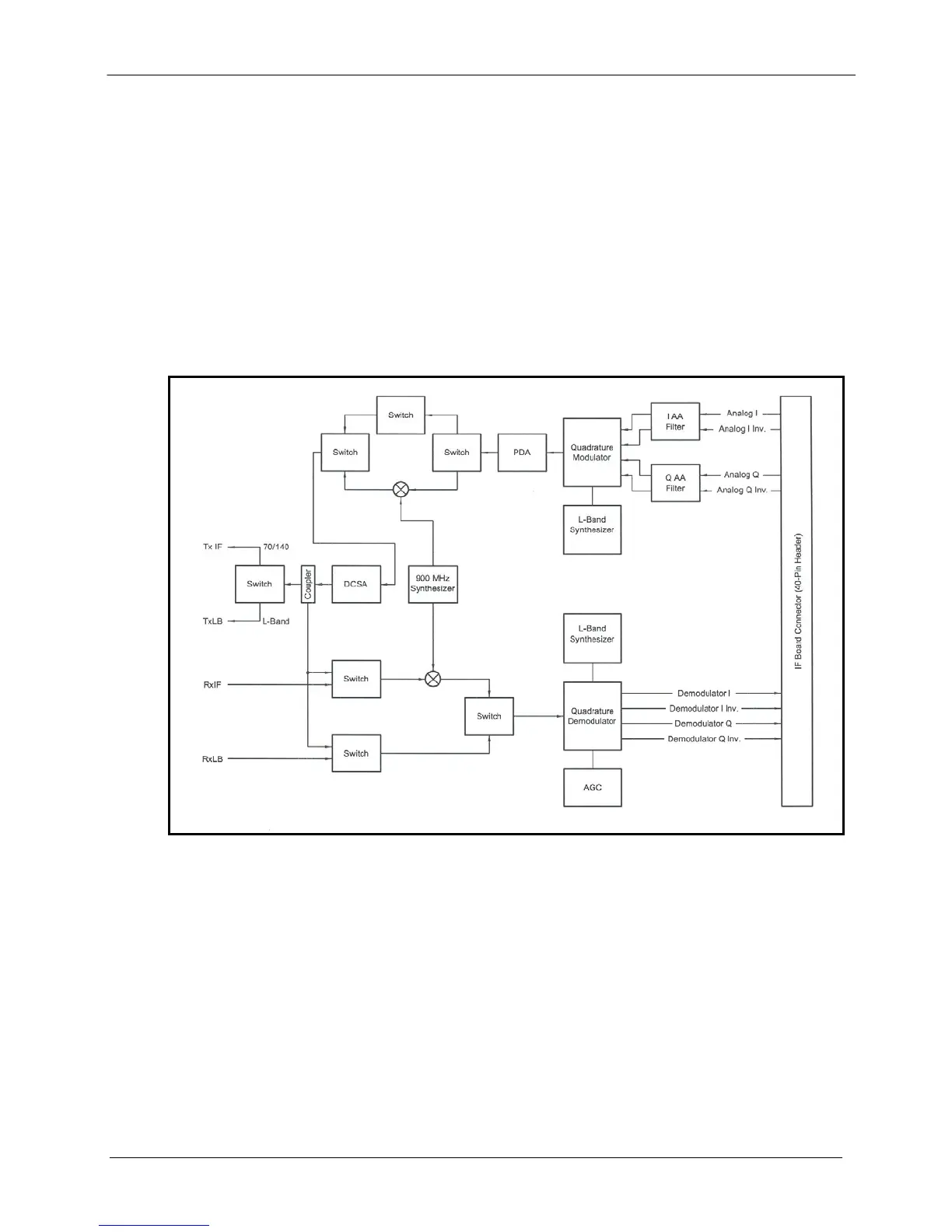
The L-Band/IF Printed Circuit Card consists of an analog modulation function, an analog complex
down conversion, and two wide-band digital synthesizers. The block diagram of the L-Band/IF
Assembly is shown in Figure 3-2.
In the modulator, analog in-phase (I) and quadrature (Q) signals are generated on the Digital
Baseband Printed Circuit Card, routed to the L-Band/IF Printed Circuit Card, and modulated at
the desired frequency. The L-Band or 70/140 modulated signal is then passed through a
microprocessor controlled variable attenuator providing gain control of the output signal.
In the complex downconverter, the signal for demodulation is amplified and sent through a
variable wideband attenuator for AGC. The gain-controlled signal is then passed through a
complex downconverter to a low IF.
Figure 3-2 IF Card Block Diagram


 To Next Page