18
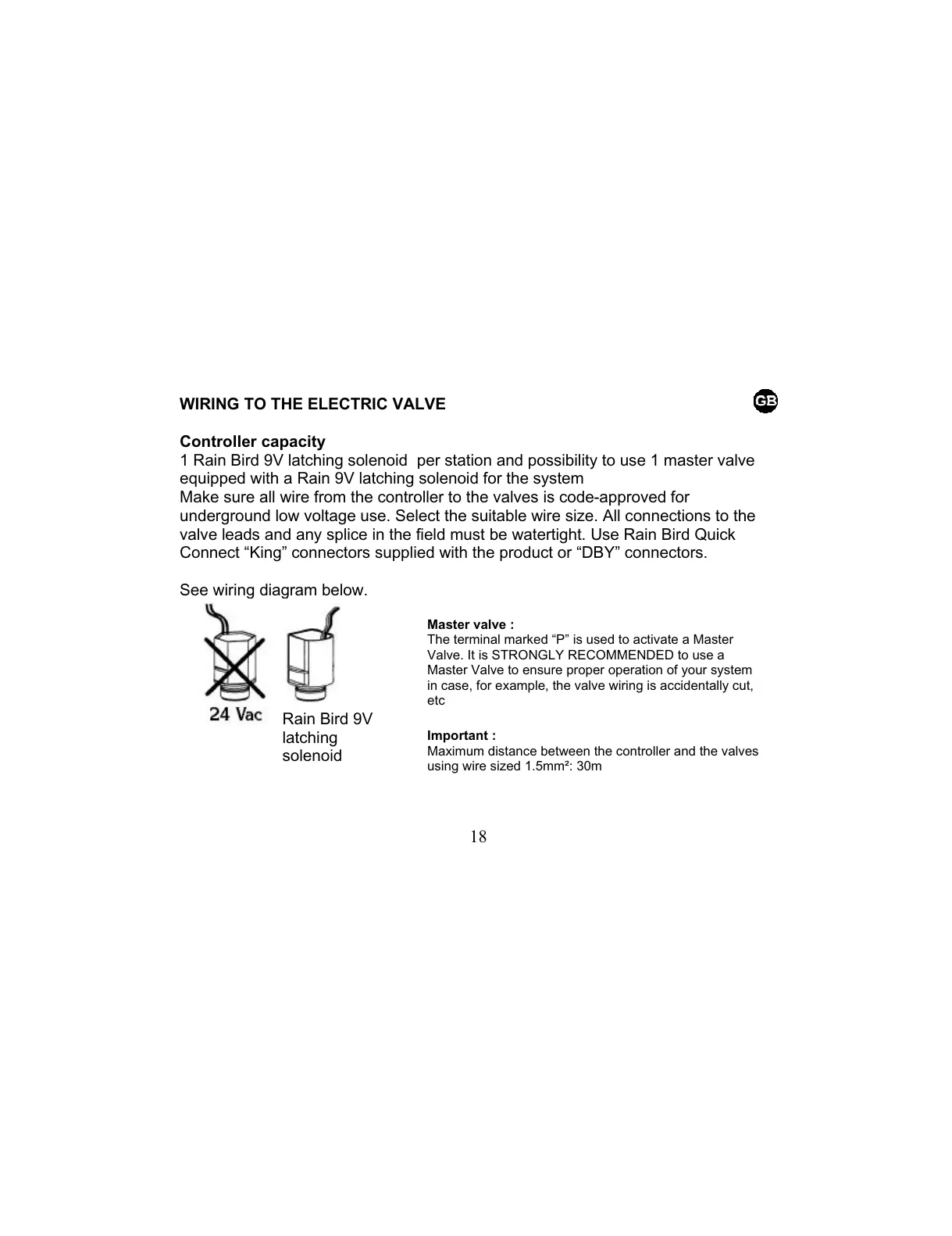
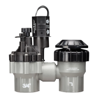
Master valve :
The terminal marked “P” is used to activate a Master
Valve. It is STRONGLY RECOMMENDED to use a
Master Valve to ensure proper operation of your system
in case, for example, the valve wiring is accidentally cut,
etc
Important :
Maximum distance between the controller and the valves
using wire sized 1.5mm²: 30m
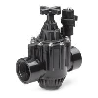
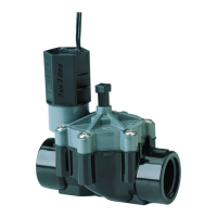
WIRING TO THE ELECTRIC VALVE
Controller capacity
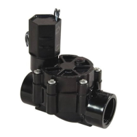
1 Rain Bird 9V latching solenoid per station and possibility to use 1 master valve
equipped with a Rain 9V latching solenoid for the system
Make sure all wire from the controller to the valves is code-approved for
underground low voltage use. Select the suitable wire size. All connections to the
valve leads and any splice in the field must be watertight. Use Rain Bird Quick
Connect “King” connectors supplied with the product or “DBY” connectors.
See wiring diagram below.
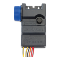
Rain Bird 9V
latching
solenoid