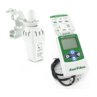
WR2-48 Wireless Sensor
5
Irrigation Modes
Programmed Irrigation
WR2 Wireless Sensor is actively managing
the irrigation
controller / timer.
Once a set point
is satised by
environmental conditions, or the “Quick
Shut O ” feature is activated, irrigation is
suspended. An X and corresponding trip
indicator (rainfall, temperature, or both)
will automatically display when irrigation is
suspended.
48-Hour Irrigation Hold Active
WR2-48 Model Only
Irrigation will be prevented
for 48 hours following
measured rainfall. The
display shall ash an X to
indicate the irrigation hold.
Override Sensor for 72 Hours
NOTE: Selecting Override Sensor cancels
any 48-hour hold
on irrigation.
User has elected
to permit
irrigation in accordance with the timer
schedule regardless of environmental
conditions (i.e. rainfall or low temperature
is detected by the sensor). System will
automatically resume programmed
irrigation mode after 72 hours (Note: X
and trip indicator will be displayed when
returning to programmed irrigation mode if
set points are satised).
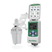
Synchronize
the Sensor and
Controller Interface
After the Controller Interface is wired
to the irrigation timer, the Sensor and
Controller Interface need to establish a
radio communication link. When the link
is established, the Sensor and Controller
Interface are considered “paired.”
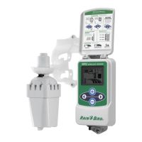
1. On the Controller
Interface, push
and hold both
arrow buttons
simultaneously to
begin the installation sequence.
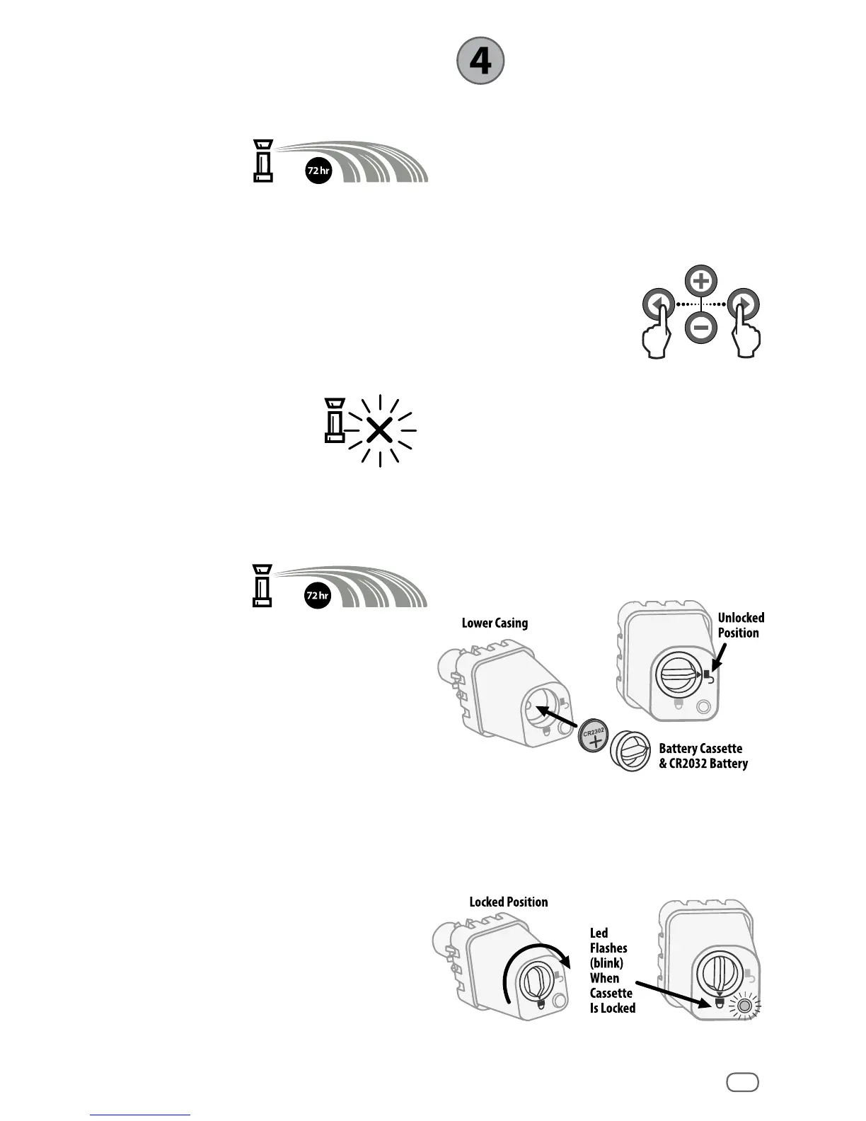
2. After the “Sensor Indicator / Pairing
Status” icon ashes, remove the label
from the bottom of the sensor.
3. The ashing “Sensor Indicator / Pairing
Status” icon prompts you to insert the
battery cassette with battery into the
Sensor lower casing as shown. Align the
arrow on the battery cassette with the
unlocked indicator on the bottom of the
Sensor.
4. Rotate the battery cassette clockwise
until the arrow points toward the locked
indicator. The light on the bottom of the
Sensor will blink once to indicate that
the sensor is now powered up.
 Loading...