1
2
4
3
5
7
8
6
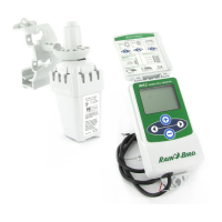
WR2-48 Wireless Sensor
2
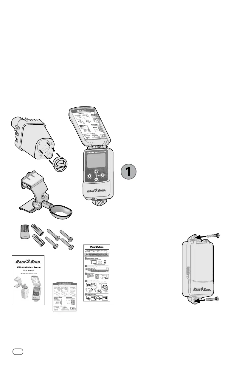
WR2 Components
A
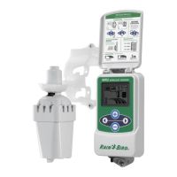
Controller Interface
B
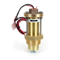
Sensor
C
Battery Cassette and Lithium CR2032
Battery
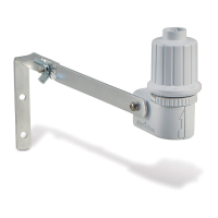
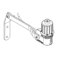
D
Sensor Mounting Bracket Assembly
E
Mounting Hardware
F
User’s Manual
G
Quick Reference Guide
H
WR2-48 Quick Reference Label
NOTE: Tools needed for installation:
drill, drill bit, and Phillip’s head
screwdriver.
WR2 Benefits
All settings are programmed through the
Controller Interface device
Large easy to understand icons communicate
irrigation mode and sensor status
Sensor LED indicator enables one-person
setup, reducing installation time
Battery is easy to install / replace
Aesthetic appearance - no external
antennas
Easy to install, self-levelling sensor bracket
mounts to at surfaces or rain gutters
“Quick Shut O ” interrupts active
irrigation cycle during a rain event
Enhanced antenna array provides
superior signal reliability that overcomes
most line of sight obstructions
Automatically prevents irrigation for
48-hours following a rainfall event (WR2-
48 model only).
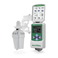
Mounting the
Controller Interface
Choose a location near the irrigation
controller / timer.
CAUTION: The cable harness is 30
inches (76.2 cm) long, so before
mounting the device, ensure the wires
easily reach the irrigation controller’s
connection terminals.
Select a at surface
adjacent to the irrigation
controller.
For best performance,
the Controller Interface
should be installed at
least ve feet (1.5m)
above the ground.
It is recommended that
the Controller Interface
be installed away from
sources of electrical interference (such
as transformers, generators, pumps, fans,
electrical meter boxes) and metal objects
to maximize communication range.
Use the mounting hardware supplied.
Attach the Controller Interface to the wall.
 Loading...