Unpack the unit and place it at the location where you intend to install it.
Stand back and look at the filter to make sure it is standing straight up and not
tilted to one side. Sometimes during shipment, the bottom of the tank will get
knocked out of alignment and you will need to straighten it out before starting
installation. If your tank is a bit tilted, simply pick the tank up 2 – 3 inches off
the floor and drop it gently but firmly down, favoring the side that needs to be
adjusted to make the filter stand straight up again.
Make sure your chosen location is fairly level, dry, and protected from possible
freezing conditions.
DO NOT set the tanks onto make shift platforms as this may cause the filter to
topple.
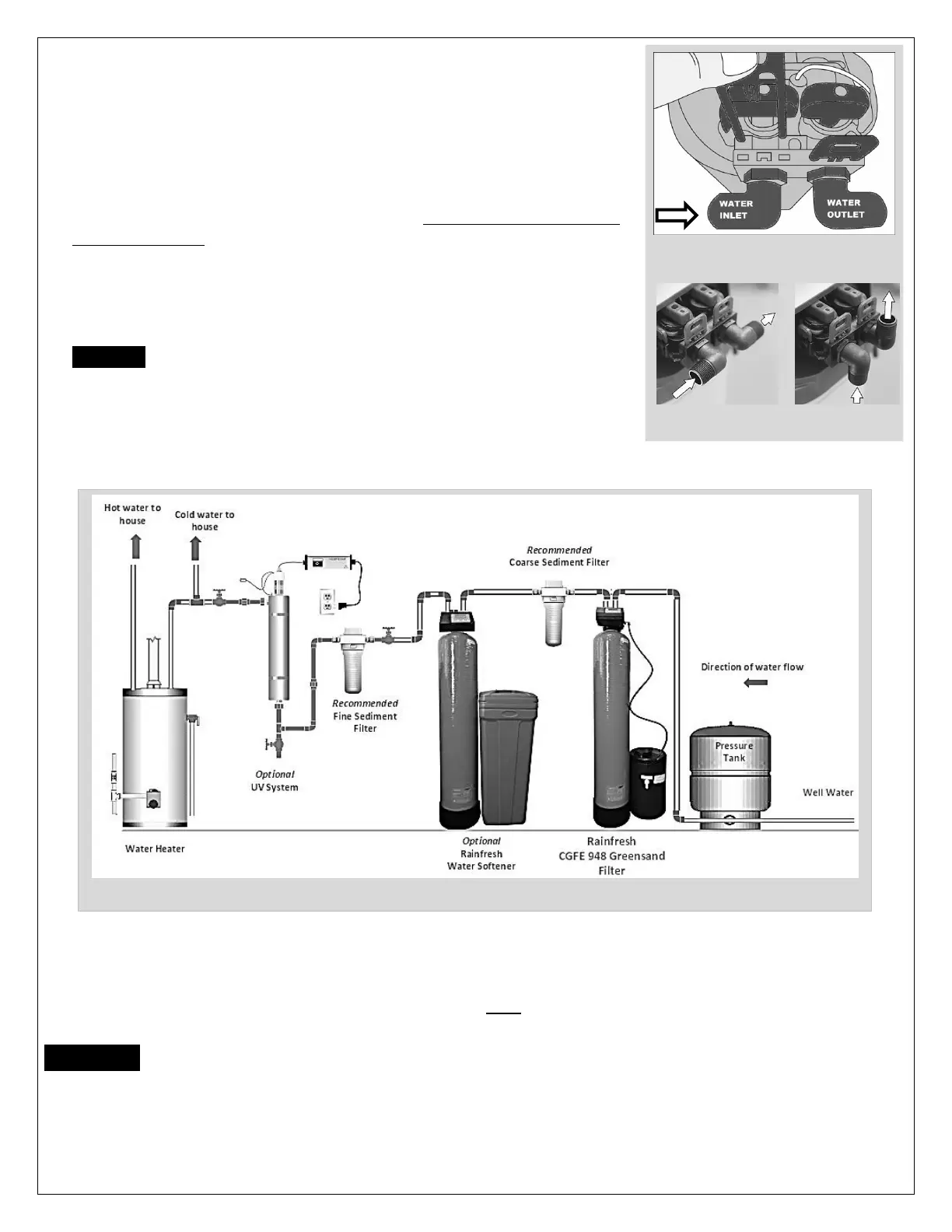
The system has 3 connections - an inlet, an outlet, and a drain line connection. If
you are looking at the back of the unit (Fig 1 & 1A), the inlet is on the left side.
WARNING: REVERSING THE CONNECTIONS WILL RESULT IN FILTER MEDIA
BEING THROWN INTO YOUR HOME'S PLUMBING SYSTEM CAUSING DAMAGE
TO IT AS WELL AS THE Filter system.
You can use copper, CPVC, PVC or PEX to install your new system
Installation Location
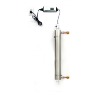
You may choose not to treat the water spigots that go outside used for irrigation or sprinkler systems. You will have to
plan the job so that you cut in to feed the CGFE filter AFTER these spigots. Installing the CGFE filter after the pressure
tank on a well water system is the preferred location. If you intend to install a water softener for soft water or a UV
system for disinfecting the water, these should be installed after the CGFE filter (see Fig 2)
CAUTION : BEFORE YOU BEGIN INSTALLATION, CONFIRM THE INLET AND OUTLET OF THE UNIT
AND IDENTIFY THE SERVICE AND BYPASS POSITIONS OF THE VALVE. The bypass valve is used to isolate
the unit from the plumbing system in order to perform maitenance or repairs on the unit. During normal use the bypass
valve should be in “SERVICE” position and to isolate it, the valve should be turned to “BYPASS” position.