Power sensor tour
R&S
®
NRT-Z14/44
19Getting Started 1443.8632.02 ─ 01
4 Power sensor tour
This chapter provides an overview of the available connectors of the power sen-
sor.
The meanings of the labels on the product are described here and in Chapter 1.2,
"Labels on the product", on page 7.
1
2
3
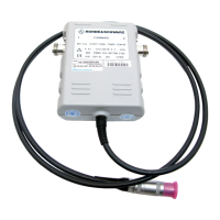
Figure 4-1: R&S
NRT
‑
Zxx directional power sensor, front side
1 = port 1 (RF connector) → connect to source
2 = port 2 (RF connector) → connect to load
3 = host interface
4.1 RF connectors
Always switch off the RF power before touching the RF connectors. See "Con-
necting directional power sensors" on page 6.
The RF connectors are used for connecting the power sensor between source
and load. To help connecting the power sensor correctly, the RF connectors are
assigned a number, indicated on the front label, see Figure 4-1.
See Chapter 3.4, "Connecting to source and load", on page 14.
RF connectors

 Loading...