31
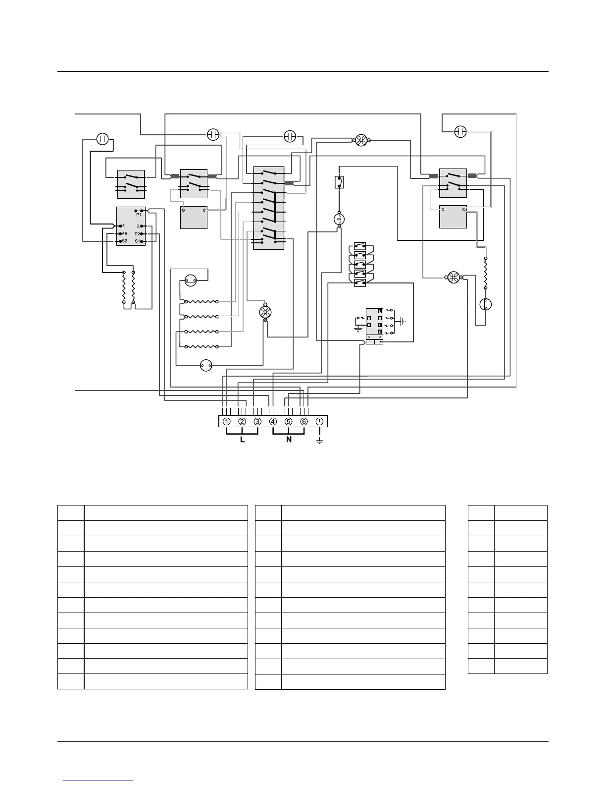
14. Circuit Diagram
1 2
P028728
6
P6
5 P5
4
P4
7 P7
8 P8
2
P2
1
P1
3 P3
P095199
1
2
P2
P1
1 2
P095199
1
2
P2
P1
E
P095199
1
2
P2
P1
a
b
e
f
c
d
1
2
or
y
v
y
or
v
v
v
br
br
bk
wb
w
w
b
b
b
b
br
v
v
b
bk
bk
b
b
b
br
w
br
b
r b
b
w
w
y
y
or
w
gr
r
r
br
or
y
r
w
gr
b
b
b
b
b
bb
b
b
b
b
r r
r
br
b
br
br
r
v
r
y
bk
bk
bk
v
b
b
b
b
b
v
A1
A2
A3
B1
B2
B3
B6
B7
B8
G
C1
B5
I
B4
C2
C3
C4
G
G
H
H
H
J1
J2
G
F2
F1
Code Colour
b Blue
br Brown
bk Black
or Orange
r Red
v Violet
w White
y Yellow
g/y Green/yellow
gr Grey
Code Description
A1 Grill Front Switch
A2 Grill Energy Regulator
A3 Grill Elements - Left-hand / Right-hand
B1 Left-hand Oven Thermostat Switch
B2 Left-hand Oven Thermostat
B3 Left-hand Multifunction Switch
B4 Left-hand Oven Top Element (Outer)
B5 Left-hand Oven Top Element (Inner)
B6 Left-hand Oven Fan Element
B7 Left-hand Oven Base Element
B8 Left-hand Oven Fan
Code Description
C1 Right-hand Oven Front Switch
C2 Right-hand Oven Thermostat
C3 Right-hand Oven Element
C4 Right-hand Oven Fan
F1 Oven Light Switch
F2 Left-hand Oven Light
G Indicator Neon
H Oven Thermal Preset
I Cooling Fan
J1 Gas Tap ignition Switch
J2 Spark Generator
Key
The connections shown in the circuit diagram are for single-phase. The ratings are for 230 V 50 Hz.