30
INSTALLATION
Check the appliance is electrically safe when you have nished.
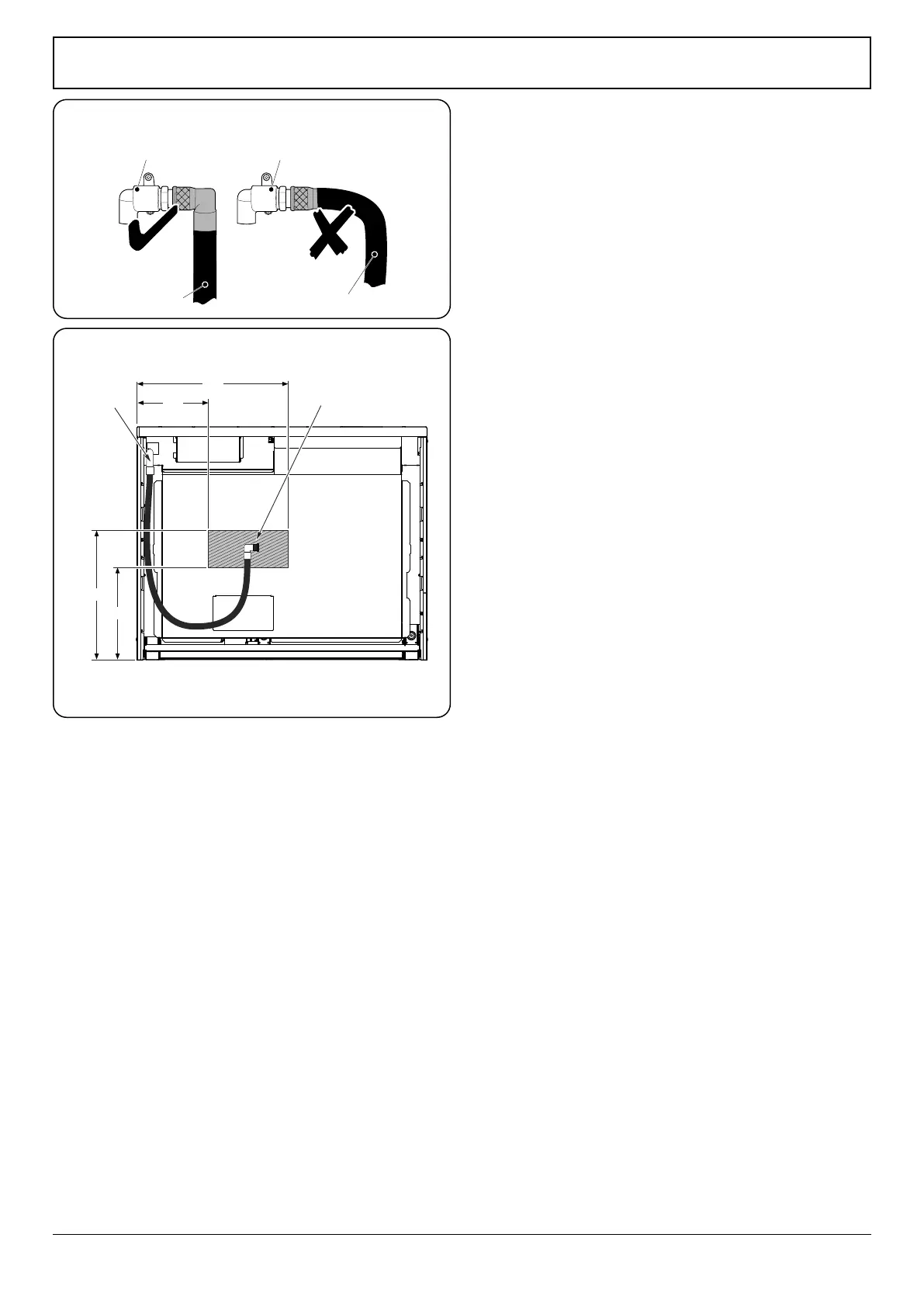
470
350
675
A
315
All dimensions in millimetres
Gas inlet
Flexible hose
PipeworkPipework
Flexible hose
Conversion to Another Gas
If the appliance is to be converted to another gas do the
conversion at this point. See ‘Conversion to LP Gas’.
Gas Connection
This must be in accordance with the relevant standards.
The exible hose (not supplied with the cooker) must be
in accordance with the relevant standards. Hoses may be
purchased at most builders’ merchants.
We recommend that a Micropoint gas hose is used when
installing this appliance.
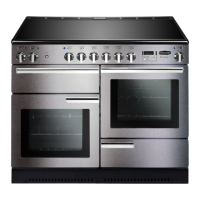
The gas supply needs to terminate with a down facing
bayonet (Fig. 9.11).
The connector is located just below the hotplate level at the
rear of the cooker. If in doubt contact your supplier.
The rear cover boxes limit the position of the supply point.
Because the height of the cooker can be adjusted and
each connection is dierent, it is dicult to give precise
dimensions.
Although a 900 mm hose can be used, a 1250 mm hose
will allow slightly more exibility in the positioning of the
bayonet and make moving the cooker easier.
The hose should be tted so that both inlet and outlet
connections are vertical so that the hose hangs downwards in
a ‘U’ shape.
Ideally the hose supply connection should be within the
shaded area ‘A’ (Fig. 9.12).
For Natural Gas, the exible hose must be in accordance with
BS 669. For LP Gas, it should be capable of 50 mbar pressure
and 70 °C temperature rise. If in doubt contact, your supplier.
Screw connect the threaded end of the hose into the gas
inlet.
After completing the gas connection, make sure that the
cooker is gas sound with a pressure test.
Pressure Testing
The gas pressure can be measured at one of the hotplate
burner injectors (not a wok burner).
Lift o a burner head. Fit the pressure gauge to the injector.
Turn on and light one of the other hotplate burners.
Turn on the control knob for the burner with the pressure
gauge tted to let gas through.
See the data badge for test pressures.
Turn o the burners. Make sure that you reassemble the
burner top in the correct way on the burner body.
Fig. 9.11
Fig. 9.12