21
OPERATION
Upper Link Compression Loads: As the equipment is
pulled through the soil, the draft caused by soil
resistance tends to rotate the equipment upward
around the lower link hitch points. This draft creates
a pushing or compressive force on the upper link.
When changes in soil resistance cause the draft to
increase, the compression force on the upper link
will also increase or decrease. These changes in
upper link compression, signal the hydraulic system
through internal linkage, to raise or lower the
equipment to maintain uniform draft.
WARNING: Do not transport or
attach equipment when the hydraulic
system is in draft control. Use position
control.
WARNING: Always lower the hydraulic
lift and all other hydraulic equip ment
before stopping the tractor.
RANSOMES tractors having the Hydraulic Draft
Control option are equipped with two lever hydraulic
lift control systems. The operation of each system is
described below
TWO LEVER CONTROLS
POSITION CONTROL OPERATION
The two lever control system is shown in Figure 28
Position control is obtained by placing the rear
(draft) control lever in the down position and then
moving the front (Position) control lever to position
the equipment as desired. The front (position) lever
is used to raise or lower the equipment.
DRAFT CONTROL OPERATION
Draft control is obtained by placing the position
control lever in the down position. Use the draft
control to adjust the draft setting (the lift system will
automatically maintain the selected draft as
described above).
OPERATING IN BOTH POSITION AND DRAFT
CONTROL
The position control may be used together with the
draft control as follows
1. Set the position control lever at the maximum
desired implement depth. The hydraulic system
will not lower the implement below the pre
selected depth. (This will also prevent “diving”
which may be encountered with light equipment,
such as a rear blade, when grading or
backfilling.)
2. Adjust the draft control lever for the maximum
draft load (pull) desired.
The hydraulic lift system will now provide normal
draft response within the range set by the position
control. This adjustment provides a more uniform
depth while maintaining an even pull in widely
varying soil conditions.
WARNING: Make sure the area is
clear of people before lowering
equipment.
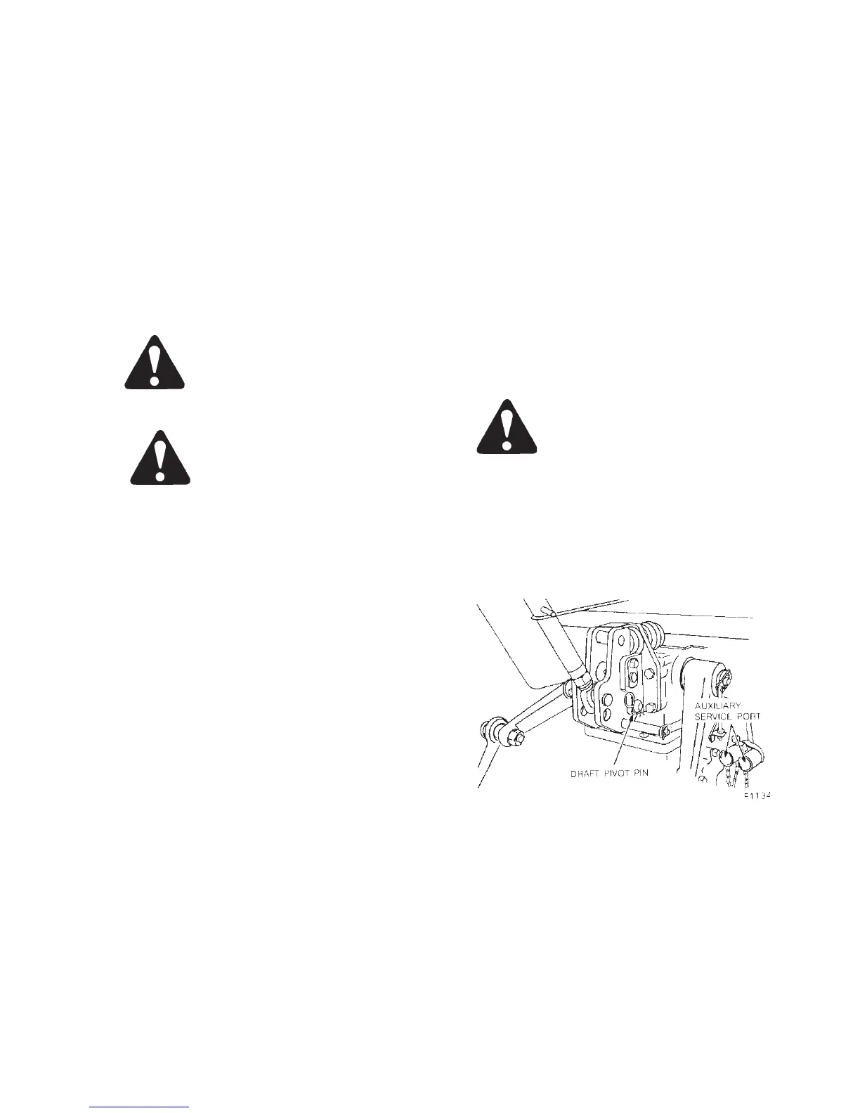
HYDRAULIC LIFT ROCKER
The hydraulic lift rocker, Figure 29, has two holes for
attaching the upper link. Attach the link in the lower
hole, as shown, for light draft loads (cultivating) and
in the top hole for heavier draft loads (ploughing).
Figure 29 - Hydraulic Lift Rocker
NOTE: Fix the draft-arm with pin, Figure 29, when
operating equipment without draft control.