22
OPERATION
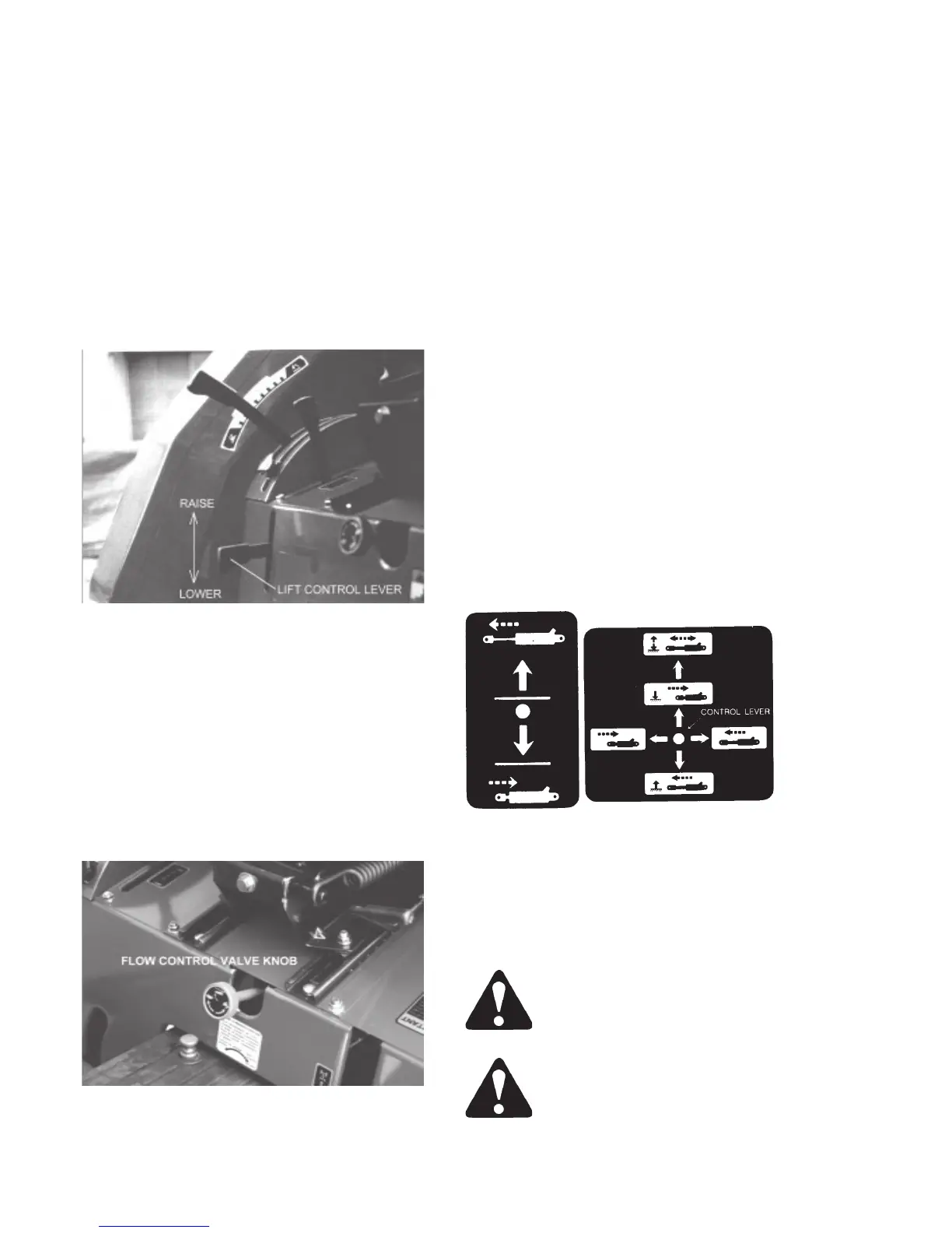
FLOW CONTROL LEVER (CT333 only)
The tractor hydraulically lifts and lowers impements.
The lever in detented in the neutral and work
position. If the lever is raised to lift the implement it
will automatically return to neutral when released
stopping the implement at that position.
CAUTION: Do not keep the lever in the raise
position for to long. It causes damage to the
hydraulic system of the tractor.
Fig 30A - Lift Control Lever
FLOW CONTROL VALVE
The flow control valve, Figure 30, provides an
adjustment to regulate the flow of oil from the lift
cylinder, thus slowing or increasing the rate of drop
of the lower links. To adjust rate of flow, either turn
the flow control valve “IN” (clockwise) to decrease
the rate of drop or “OUT” (counterclockwise) to
increase the rate of drop. The flow control valve
must be opened before hydraulic lift control will
function.
Figure 30 - Flow Control Valve
OPERATING REMOTE CONTROL VALVES
(OPTIONAL)
Your RANSOMES Tractor can be equipped with a
single and/or double spool remote control valves.
Figure 31 shows the operation of the single spool
and double spool valves.
On the single spool valve (CT333 std.), pull the
control lever rearward to extend the cylinder. Push
the control lever forward to retract the cylinder.
Release the control lever to stop the cylinder in any
position before it is fully extended. The lever returns
to neutral automatically.
For the double spool valve pull the control lever
rearward or push it sideways to the right to extend
the cylinder. Push the control lever forward or pull it
sideways to the left to retract the cylinder. Release
the control lever to stop the cylinder in any position
before it is fully extended. The lever returns to
neutral automatically. Fully forward past detent
position is a “FLOAT” position which allows a
cylinder to extend or retract freely.
Single Spool Double Spool
Figure 31 - Operating Remote Control Valve
NOTE: The lever of single spool remote control
valve is shown in Figure 28. The tubing coupler
location for this valve option is shown in Figure
29.
WARNING: Before disconnecting
cylinders or equipment, make certain
that the implement or equipment is
supported securely.
WARNING: Remote couplers must be
properly mounted and securely
fastened to tractor mounting bracket for
proper function of safety disconnect