Page 6
S01-S04
S05-S08
S09-S12
2003
2004
COMMAND CENTER 1
COMMAND CENTER 2
2001
2002
PHONE 1
PHONE 2
PHONE 3
PHONE 4
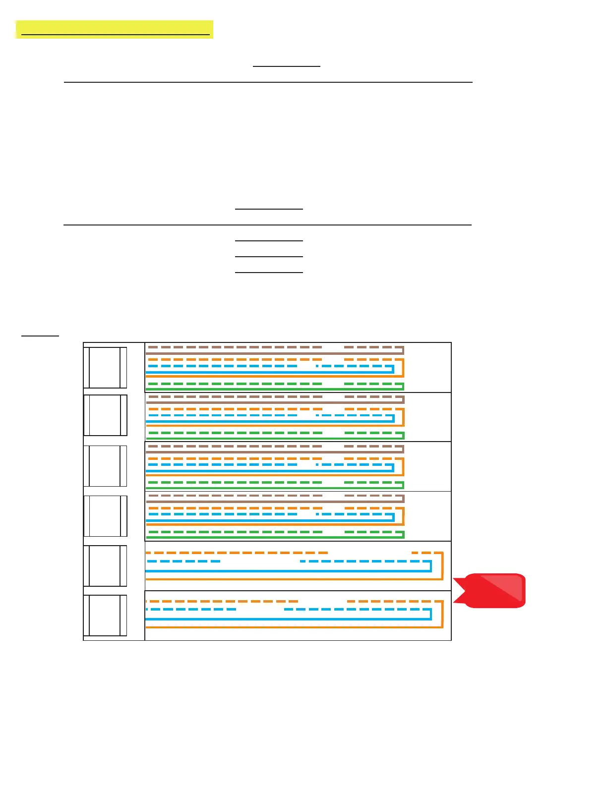
Note: Do not use
the green and
brown pairs
S13-S16
D1-2 T1-2
2007
2008
2005
2006
PHONE 5
PHONE 6
PHONE 7
PHONE 8
2011
2012
2009
2010
PHONE 9
PHONE 10
PHONE 11
PHONE 12
2015
2016
2013
2014
PHONE 13
PHONE 14
PHONE 15
PHONE 16
TELCO LINE 1
TELCO LINE 2
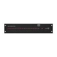
Option 2: 64-128 Zone VoIP Systems
• On top of each RJ45 interface there is a label indicating connection:
• S01-S_ is the port used for connecting HARDWIRED Emergency Phones
IP EMERGENCY PHONES DO NOT CONNECT TO THE DISTRIBUTION MODULE
• TD (1-2)(3-4) with a dot under the D is the port used for connecting Command Center Phone(s)
• TD (1-2)(3-4) with a dot under the T is the port used for outside Telco Line
• Plug the supplied RJ45 pigtail cables into the RJ45 interface connections following the wiring chart and pin-out
color scheme below
• Refer to the top of the cards to see what type of RJ45 interface and number of extensions
• The system uses T568-A for pin-out wiring
• The rst card installed will always be:
• Port 1: (S01-S04) Connection for 4 HARDWIRED Emergency Phones
IP EMERGENCY PHONES DO NOT CONNECT TO THE DISTRIBUTION MODULE
• Port 2: (S05-S08) Connection for 4 HARDWIRED Emergency Phones
• Port 3: (S09-S12) Connection for 4 HARDWIRED Emergency Phones
• Port 4: (S13-S16) Connection for 4 HARDWIRED Emergency Phones
• Port 5: (D1-2) Connection for up to 2 Command Center Phones
• Port 6: (T1-2) Connection for up to 2 Outside Telco Lines
Card 1:
Once all RJ45 connections are made, connect twisted, shielded pairs onto the pigtail sides of the wiring harnesses.
7. Turn on the 120vac power supply (if not already done).
8. Turn on the Distribution Module.