Distribution Module Wiring
Option 1: 1-48 Zone VoIP Systems
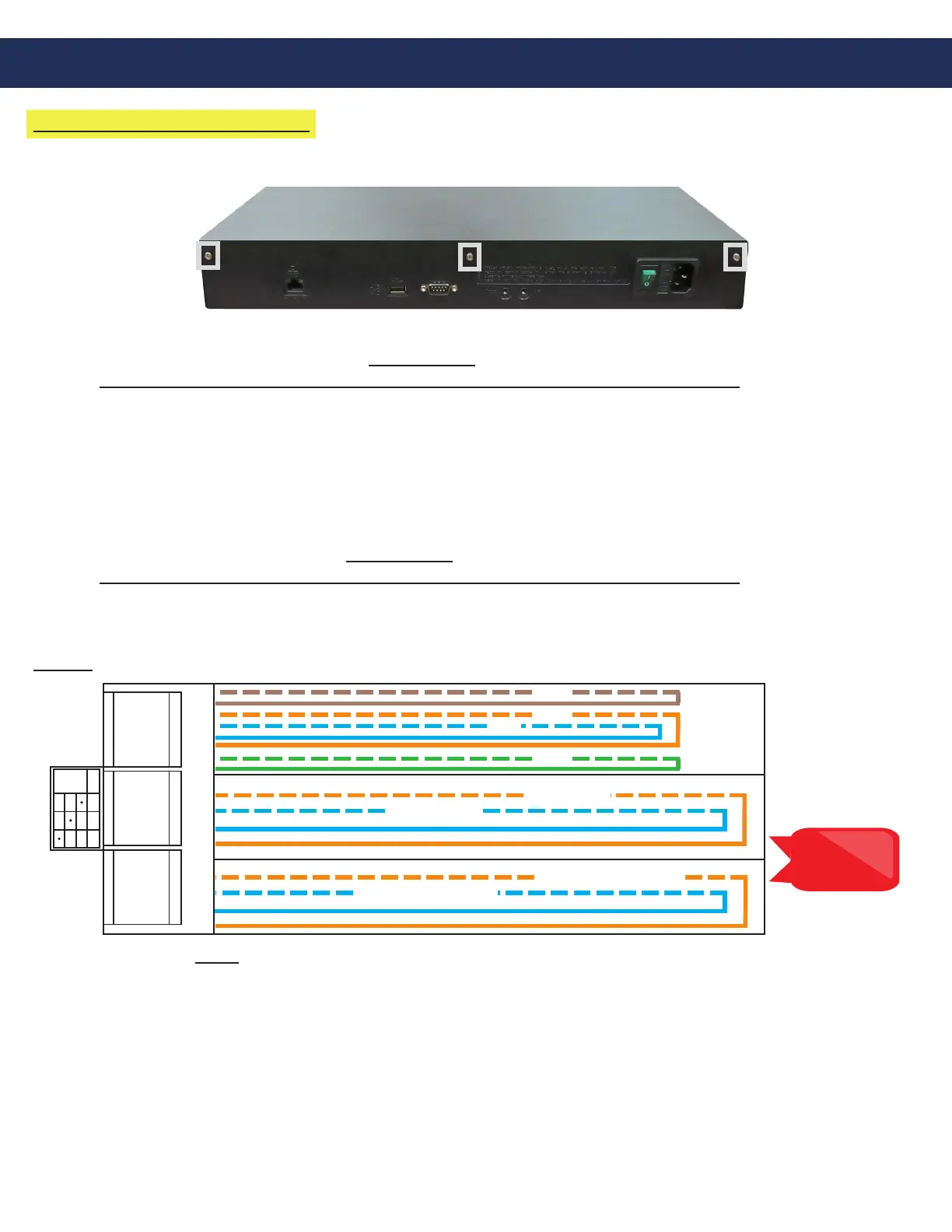
For 1-48 zone systems, remove the screws on the back of the Distribution Module and remove the cover to expose
the internal RJ45 connections.
• On top of each RJ45 port, there is a label indicating connection:
• SLT is the port used for connecting HARDWIRED Emergency Phones
IP EMERGENCY PHONES DO NOT CONNECT TO THE DISTRIBUTION MODULE
• DKP is the port used for connecting the Command Center Phone
• TWT is the port used for outside Telco Line
• Plug the supplied RJ45 pigtail cables into the RJ45 connections on the Distribution Module following
the wiring chart and pin-out color scheme below
• Refer to the top of the cards to see what type of RJ45 port and number of extensions
• The system uses T568-A for pin-out wiring
• The rst card installed will always be:
• Port 1: (01-04) Connection for 4 HARDWIRED Emergency Phones (SLT)
IP EMERGENCY PHONES DO NOT CONNECT TO THE DISTRIBUTION MODULE
• Port 2: (05-06) Connection for 2 Telco Lines (TWT)
• Port 3: (07-08) Connection for up to 2 Command Center Phones (DKP)
Card 1:
S01-S04
S05-S06 S07-S08
2003
2004
COMMAND CENTER 1
SLT TWT DKP
01 - 04
05 - 06
07 - 08
COMMAND CENTER 2
TELCO LINE 1
TELCO LINE 2
2001
2002
PHONE 1
PHONE 2
PHONE 3
PHONE 4
Note: Do not use
the green and
brown pairs
Note: DO NOT plug anything into the sixth card labeled “VMS”.
• Once all RJ45 connections are made, connect twisted, shielded pairs onto pigtail sides of the wiring harnesses
Page 5