Page 7
Connecting System to Network
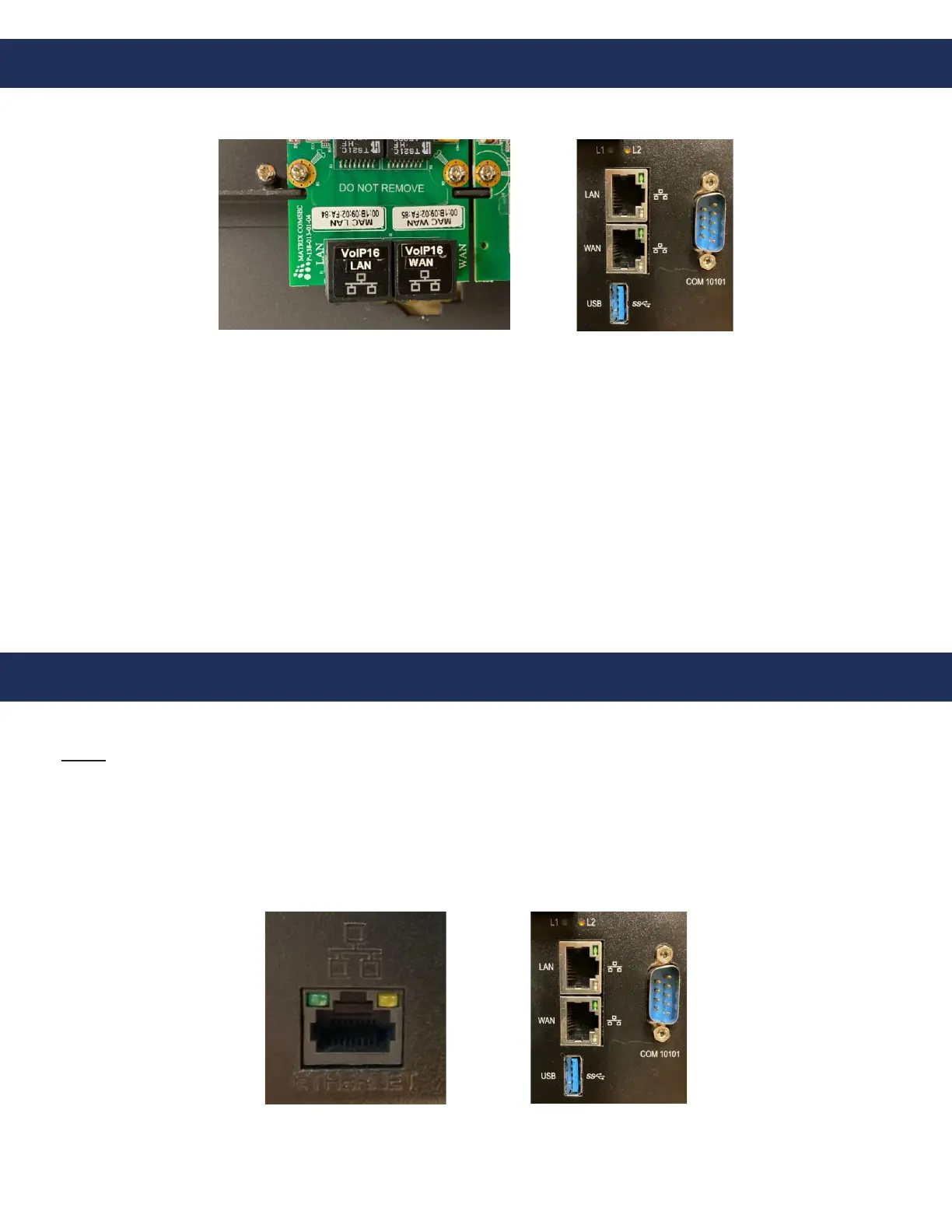
9. Connect the Ethernet cable from the WAN port on the VoIP Card on the Distribution Module to the router.
VoIP Card Programming
11. Program the VoIP card:
Note: If network information is provided to RATH® at the time of purchase, no additional information needs to be
entered for the VoIP card. If network information is NOT provided, the following needs to be performed:
a. Connect the Ethernet port of the Distribution Module to your Windows laptop using an Ethernet cable
• For 1-48 zone systems, the Ethernet port is located on the back of the housing (same side as the power switch)
• For 49-128 zone systems, the LAN Port is used
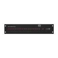
10-48 Zone
64-128 Zone
10-48 Zone 64-128 Zone
10. Connect Emergency Phones to the system:
a. IP Phones:
• Connect the Ethernet cable from the POE port on the emergency phone to the POE+ switch
• CAT5e or CAT6 is recommended
• Do not exceed the maximum wire run length of 320’
b. Elevator Phones (Analog Phones with IP Interface):
• Connect the Ethernet cable from the IP Interface to a network switch (do not exceed the 320’ maximum
wire run length)
• Connect the two-wire line cord from the LINE output on the IP Interface to the phone line input on the
Elevator Phone board
• CAT5e is the minimum standard cable for the system (please check with your local AHJ to ensure
compliance with state and/or local codes)