Do you have a question about the Raven Spra-Coupe SCS 460 and is the answer not in the manual?
Guidelines for mounting the radar speed sensor to the vehicle frame.
Instructions for positioning the flow meter and optional pressure transducer.
Procedures for mounting the motorized control valve in the main hose line.
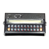
Steps for securing the console and routing its cables within the vehicle.
Method for calculating boom width for broadcast and band spraying.
Procedure for determining and entering the speed calibration number.
Explains the valve calibration number and its digits for various valve types.
Method to determine application rates and select appropriate spray nozzles.
One-time operation to calibrate the console before initial use.
How to display various system totals and data points.
Simulates operating speed for system testing without vehicle movement.
Setting a low limit for flow rate to trigger an alarm.
Alarm activates if application rate deviates significantly from target.
Alerts when the volume in the tank drops below a set value.
Sets the increment for increasing or decreasing flow rates.
Sets a delay between boom activation and flow rate control.
Automatically shuts off flow when vehicle speed drops to a minimum.
Accesses various system features for display and configuration.
Instructions for printing field begin and end data.
Enables or disables audible alarms for system faults.
Controls how the target and actual rates are displayed.
Alerts when the Rate 1 calibration number is changed.
Allows user to enter a number to represent a field for GPS.
Explains GPS features, available when GPS is active.
Allows entry of a field number for reference.
Selectable baud rate for GPS and data logging modes.
Sets how often data logging triggers (feet or seconds).
Selects units (feet or seconds) for data logger triggers.
Enables or disables the data logging function.
Sets the zero point for the pressure transducer display.
Sets the percent of off-target value for rate alarms.
Sets the maximum desired RPM or hydraulic output for PWM valve.
Sets the minimum RPM or hydraulic output for PWM valve.
Enters the coil frequency for the PWM type valve.
Activates a code to prevent unauthorized data entry.
Step-by-step guide for mounting and calibrating the wheel drive speed sensor.
Procedures for drilling rims to mount speed sensor magnets.
Method to calculate the SPEED CAL number based on wheel revolutions.
Steps to test the functionality of speed sensor extension cables.
Procedure to test the integrity of flow meter cables.
Steps for cleaning, maintaining, and adjusting the flow meter.
Detailed steps for re-calibrating the flow meter for accuracy.
Pinout and configuration details for serial communication.
Defines communication strings for the SCS 460 console.
| Model | SCS 460 |
|---|---|
| Manufacturer | Raven |
| Input Voltage | 12 V DC |
| Display | LCD |
| Type | Controller |
| Function | Controls application rate for sprayers |
| Connectivity | CAN |
| Mounting | Cab mount |