EasyManua.ls Logo

RAYLASE AXIALSCAN - Interfaces of the linear translator module; Analog input

Default Icon
71 pages
Print Icon
To Next Page IconTo Next Page
To Previous Page IconTo Previous Page
Loading...
Chapter 4 Functional description
28 RAYLASE 3-Axis Subsystems for Laser Beam Deflection MN025 / v2.1.0
4.6 Interfaces of the linear translator module
For subsystems with analog interface only
4.6.1 Analog input
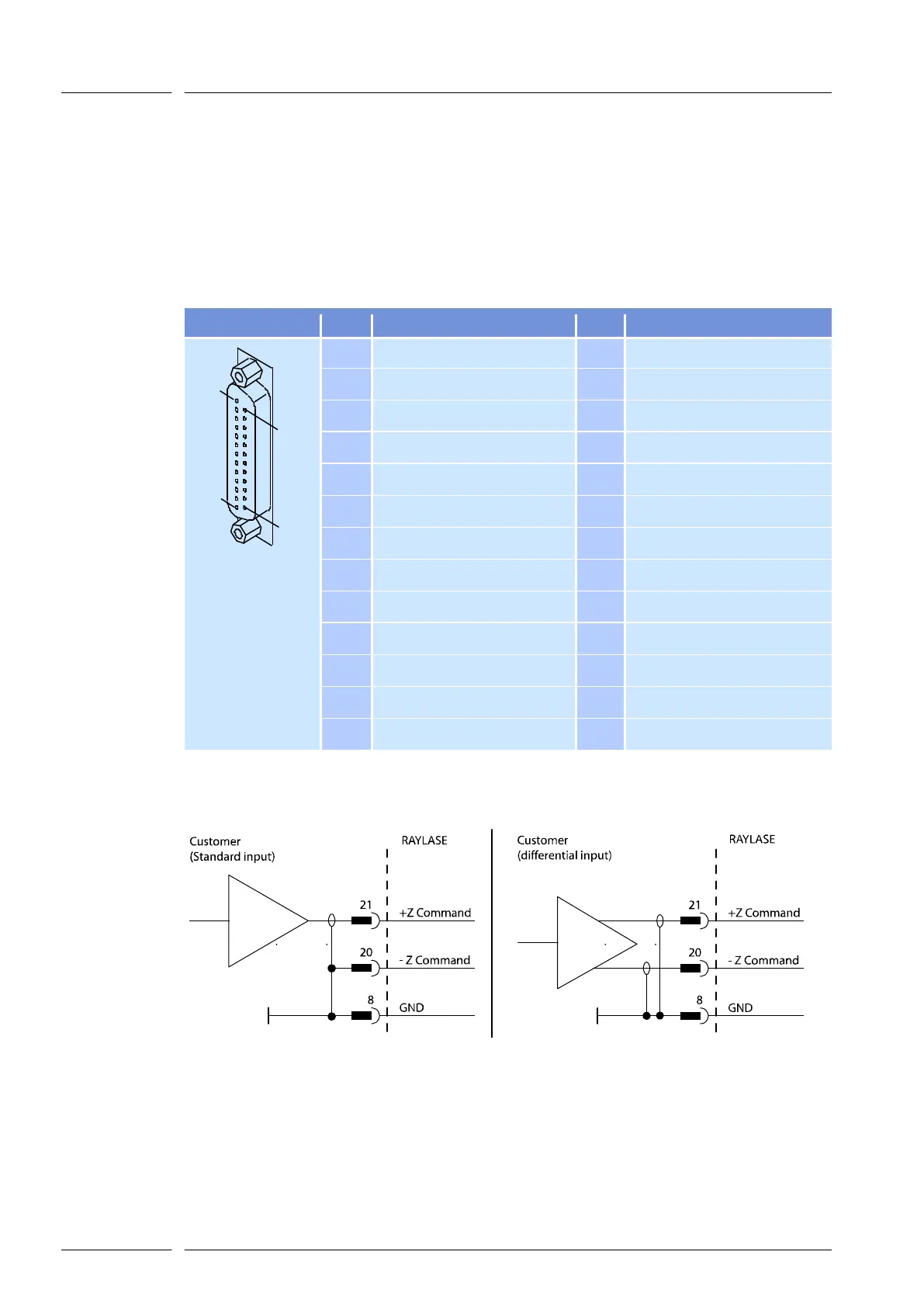
The terminal assignment of the analog interface is outlined below. To determine whether the
deflection unit is fitted with an analog or a digital interface, refer to the code on the rating plate
( page 15, Rating plate code).
PIN
Signal
PIN
Signal
1
13
25
14
25 PIN D-SUB
1
GND
14
nu
2
GND
15
nu
3
GND
16
nu
4
GND
17
nu
5
nu
18
nu
6
GND
19
nu
7
GND
20
-Z Command
8
GND
21
+Z Command
9
GND
22
Z Position
10
GND
23
/Z Temp-ok
11
/Z Ready
24
/Z Pos-Error
12
GND
25
Z Velocity
13
GND
---
---
nu = not used
To prevent errors, shielded cables should be used and signals must be input as shown below.
Fig. 13
Signal input

Table of Contents