EasyManua.ls Logo

RAYLASE AXIALSCAN - Digital output

Default Icon
71 pages
Print Icon
To Next Page IconTo Next Page
To Previous Page IconTo Previous Page
Loading...
Chapter 4 Functional description
32 RAYLASE 3-Axis Subsystems for Laser Beam Deflection MN025 / v2.1.0
For subsystems with digital interface only
4.6.5 Digital output
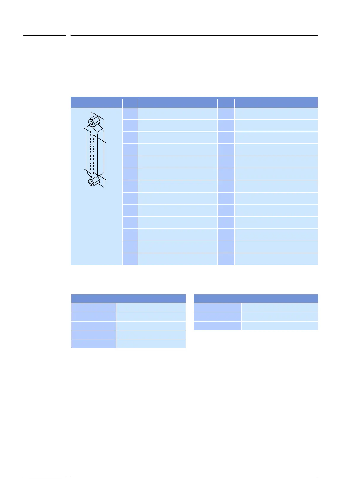
The linear translator module uses the 25-pin D-SUB female connector to transmit data to the
deflection unit and supply it with power. All signals are compatible with RAYLASE's extended
function XY2-100 standard.
PIN
Signal
PIN
Signal
1
13
25
14
25 PIN D-SUB
1
O
-SENDCLOCK
14
O
+SENDCLOCK
2
O
-SYNC
15
O
+SYNC
3
O
-X-DAC CHANNEL
16
O
+X-DAC CHANNEL
4
O
-Y-DAC CHANNEL
17
O
+Y-DAC CHANNEL
5
nc
18
nc
6
I
-HEAD-STATUS
19
I
+HEAD-STATUS
7
nc
20
nc
8
nc
21
nc
9
+VSS
22
+VSS
10
+VSS
23
GND
11
GND
24
GND
12
-VSS
25
-VSS
13
-VSS
---
---
I = Diff. Input, nc = not connected, O = Diff. Output
Specifications
Diff. Input-, Diff. Input+
-
Diff. Output-, Diff. Output+
Input voltage
5V
Output low
max. 0.6V
max. 40mA
Input threshold
200mV
Output high
min. 2V @ 50Ω
max. 40mA
Hysteresis
typ. 45mV
ESD protection
±10kV
Input impedance
120Ω
ESD protection
±15kV

Table of Contents