Chapter 5 Installation
40 RAYLASE 3-Axis Subsystems for Laser Beam Deflection MN025 / v2.1.0
Optimizing settings
o Repeat the entire adjustment process until optimum laser beam input point and input angle
settings are achieved.
5.4.3 Assembly
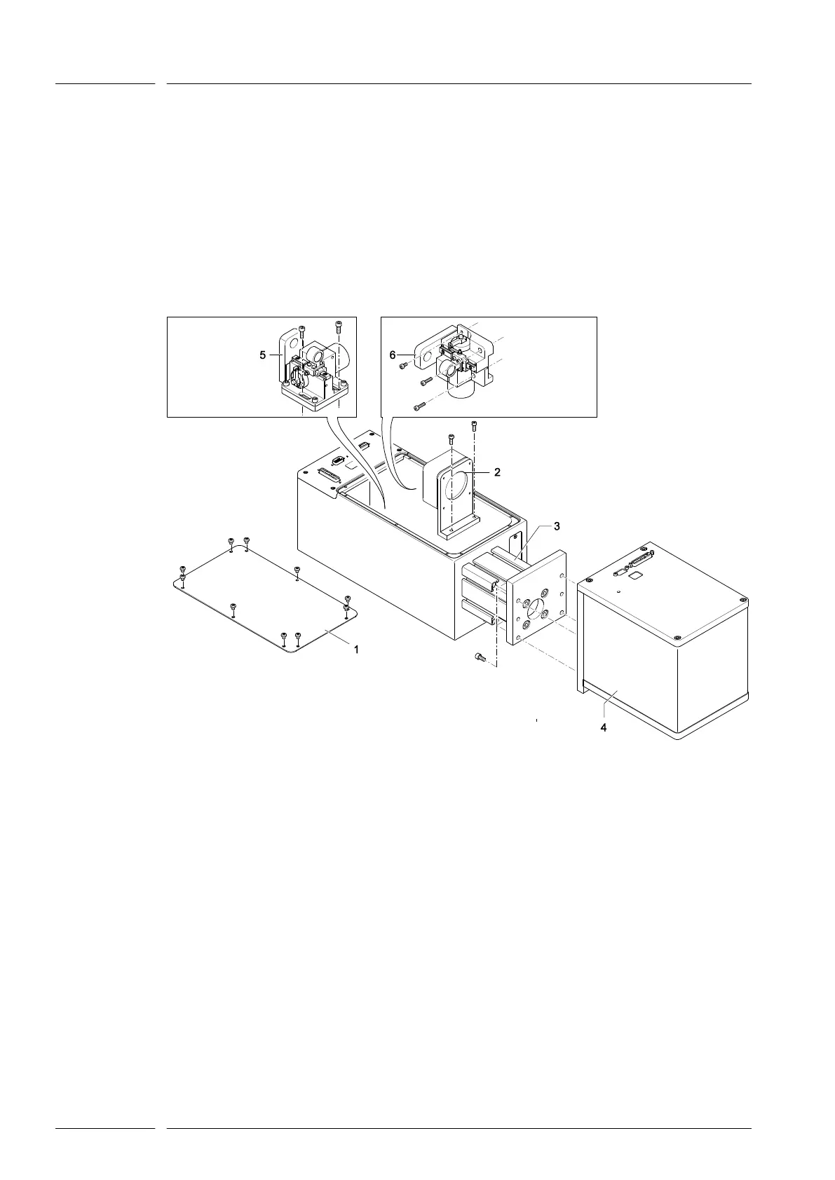
The process for assembling all of the components is as follows:
o Install the deflection unit (4).
o Install the focusing lens(es) (2). Pay attention to the corresponding markings.
o Install the linear translator, (5) or (6) depending on the model.
o If you are using a subsystem with manual field size adjustment, you now have to adjust the
field size ( page 44, Manually adjusting the field size). In subsystems with motorized field
size adjustment, this is done by the software.
o Fit the cover (1).
Fig. 18
Finalize the
checking proce-
dure
AXIALSCAN
(standard)
AXIALSCAN
(motorized)
FOCUSSHIFTER
(standard)


 To Next Page