INSTALLATION
WHEEL DRIVE UNIT
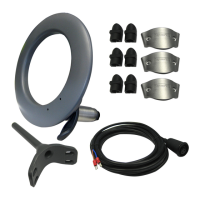
The wheel drive unit (Fig.2) is attached to
the vessel’s wheel using the clamps
supplied. To complete the installation it is
only necessary to screw the torque
restraint bracket to the pedestal. It has
been designed for permanent mounting
in the cockpit and requires no
maintenance whatsoever.
A single lever disengages drive for
manual steering.
STEERING SYSTEM
The Autohelm 4000 is designed to
operate with steering systems having
between 1 and 3.5 turns lock to lock.
Steerinq systems with more than 3.5 turns
may
ca&e
impaired steering performance
due to reduced rate of rudder application.
Lost motion in the steering system must
not exceed 1% of total movement. This is
equivalent to 7.5 degrees of free wheel
movement for a system with two turns
lock to lock. If lost motion exceeds this
level it must be corrected otherwise
steering performance will be impaired.
It is recommended that the wheel driv
L\
is not used on hydraulic steering systemi
’
Hydraulic slip across the helm pump
*-d
produces significant lost motion which
will impair steering performance.
Fig.2
WliEEICI.AMPS
I
CLUTCH LEVER
DRtVE MOTOR/GEARBOX
2
ATTACHMENT TO THE WHEEL
The drive unit is clamped to the wheel
spokes using the bolts and clamps
provided, and may be used on wheels
with 3,5 or 6 spokes (Fig. 3).
Fig.3
AI8
A holes
-
3 and 6 spoke wheels
B holes
-
5 spoke wheels
The drive unit must be mounted
between the wheel and the pedestal
(Fig. 2).
The attachment kit has three romplete
sets of clamps to compensate for differing
spoke diameters. Marked alongside each
clamp is the spoke diameter to which it
relates. The appropriate clamps are simply
broken off as required.
The spacers (Fig. 5) must be used when
the wheel is dished (Fig. 6) t9 prevent
distortion of the drive unit when the fixing
bolts are tightened.
Fig.5
SPACER
For 4 spoke wheels, use a 4.0mm
(5/32irr) drill to open out
iht>
C pilol holrs
to gain access to the additional mounting
points (Fig. 4). The plastic membrane
covering the additional nut inserts is only
1 .Omm (0.040in) thick, and care must be
tnkcn to cns\lrC that the nut inserts
arc!
ilol
ci,~tri,igotl
WIICII drilling
AI,
;Itldition~il
sol
of tlarnps
;Irld
Ml,
lot
thr
foirp
spoke is avail,Ue
IIO~TI
your Aulollgltn
stockist.

 Loading...