Since the autopilot is microprocessor
based it is very important that voltage
losses in supply cables are minimised.
Supply cables should therefore be as short
as possible and of no less size than shown
in the following table.
Lead Length
Copper Area
AWG
Up to 2.5m (8ft)
1
.Smm’
16
-----_-
Up to 4.0m (13ft)
2.5mm’
14
-_______-
To avoid the risk of confusing the power
supply and motor cables the power supply
cabling should be completed before
wiring the drive unit.
DRIVE UNIT CONNECTION
The drive unit is supplied with 4.5m (15ft)
of two core cable which is passed through
the pedestal or guard rail and connected
back to the control unit socket as follows:
l Drill 9mm (0.35in) diameter hole in.the
front face of the pedestal.
l Select one of the two grommets
supplied and use it where the drive
unit cable passes through the pedestal
W3ll.
l
Rut1
the cable down the pedestal and
sCcurC
close lo the pedestal base using
the clip provided.
l Run the cable back to the control unit
socket (Fig. 16) and connect as follows:
Fig. 16
DRIVE UNIT
EARTH POWER SUPPLY
(Blue) (Pre-wired at
\
Factory)
If it is necessary to extend the drive unit
cable, the
extensi.on
should be as short as
possible and of no less size than shown in
the following table.
Extension Cable
Copper Area
Length
’
AWG
Up to 2.5m (8ft)
1
.5mm2 16
Up to 4.0m (13ft) 2
5mm’
14
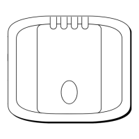
Having attached the cable to the
control unit socket, the socket may be
screwed
[n
place using the four self
tapping screws provided (Fig. 17).
Fig.17
’
Accessory Connection
The Autohelm 4000’s accessories plug
into the contrdl unit to facilitate stowing
and servicing. To ensure reliable
connection each plug incorporates a
locking ring which should be turned
clockwise to secure.
The windvane should be connected \
.’
the socket marked Vane and the
hand’bd
held remote to the socket marked
Remote.
WINDVANE
ATTACHMENT
The windvane attachment is normally
mounted centrally on the after rail where
it can be sited in clear wind on both tacks.
The windvane mounting mast is clamped
to the after rail by the two ‘U’ bolts
to allow the windvane head
tobe
plugged into the top of the mast (Fig.’ 19).
w-
‘“3e
interconnectina cable can then be
back and
plugied
into the Autohelm
Note The windvane head is supplied
with the vane detached for ease of
packing. The vane is easily assembled to
the head and secured by means of the
circlip provided (Fig. 20). Care should be
taken to ensure that the small circlio is
1
provided (Fig. 18j. The interconnecting
cable should be brouqht throuqh the slot
’
correctly located in the groove.
.
DRIVF
UNIT
CABI
E
(to be wired on
installation)
DRIVE
UNIT ‘PIN 3
(Blue to PIN 2) (Brown)
8

 Loading...