CONTROL [JNIT
ALTERNATIVE DRIVE UNIT MOUNTING
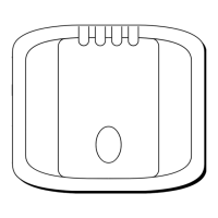
The control unit (Fig. 13) slots into a
permanently mounted socket sited in the
cockpit. It contains a gimballed fluxgate
compass and therefore has some
restrictions on mounting position.
The control unit should be sited where
it can be operated easily from the steering
position. It should also be positioned at
least 80cm
(2ft6in)
away from the main
steering compass to avoid deviation of
both compasses.
POSITIONS
The fluxgate compass is calibrated to give
correct steering sense when’ the drive
motor is facing forward.
Deviation of the control unit fluxgate
compass is less important since headings
are always adjusted by reference to the
main steering compass. Nevertheless,
deviation should be avoided if possible
and thus the control unit should be sited
as far away from other magnetic or iron
devices as practical.
If the steering wheel
arlangement
makes installation possible only with the
motor facing aft, the motor drive sense
will have to be corrected as follows.
Use a screwdriver to rotate the
changeover switch
anti-cl+kwise
until;’
.)
endstop is reached (Fig. 14). Never fot’
the changeover switch, light
pressud
only is required.
:
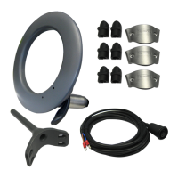
Having selected the best mounting site,
the mounting socket may be secured to a
vertical surface using the self tapping
screws provided.
Fig.13
6
CABLING AND POWER SUPPLIES
(see Fig. 15)
The four pin
v+terproof
connector
provides a pluggable connection to the
power supply and motor drive.
,
Two terminals of the socket are
pre-
wired for connection to the 12v power
supply, the drive unit cable is connected to
the remaining two terminals on
installation.
It is most important that
power supply is not connected to
drive unit terminals. If the 12v
supply is accidentally connected to
the drive unit connection terminals
permanent damage will be caused.
For this reason the pre-wired power
supply cable should not be removed from
the socket.
Before wiring the socket, select its
position and drill a
22mm
diameter hole.
Pass the prewired power supply cable
j
through the hole ready for connection to
the battery.
l-l
DRIVE UNIT
C
ABI
It
f1g.15
(4.5m (151I)SUPPLIED)
BATTERY CONNECTION
The power supply cable is pre-wired to the
socket and must be connected directly to
the vessels electrical distribution panel. It
must be independently switched and
protected by a 15 amp fuse or current trip,
and on no account paralleled into existing
wiring for other equipment.
The brown wire of the power supply
lead should be connected to positive. If
connections are accidently reversed the
Autohelm 4000 will not operate but no
damage will result.
CAB1.E
CLIP
12v SUPPLY
(SUPPLIED)
FOUR PIN CONTROL
CONNECTOR AND CABLE
(SUPPLIED)
:
PO*ER
SUPPLY
CABL
F
(2m
(HI)
SUPPLIED
(SUPPIUED)
(FROM DISTRIBUTION PANEI) (-.‘
,f~~/-c~
\.--.
-.---.-.-.,.~---
..-
-J
CIRCUIT BREAKER AND 15A FUSE

 Loading...