Do you have a question about the Raymarine Autohelm ST4000 and is the answer not in the manual?
Basic principles of autopilot operation and returning to manual steering.
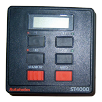
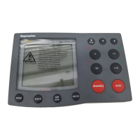
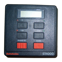
Details of the control buttons for the autopilot functions.
Controls for engaging/disengaging autopilot for hand steering.
Controls for engaging automatic steering and maintaining heading.
Controls to alter course in increments of 1 and 10 degrees.
Procedure to avoid obstacles under autopilot control.
Allows autopilot to maintain track between two waypoints using GPS/Decca/Loran.
Steer relative to apparent wind angle, eliminating turbulence effects.
Controls for switching on display illumination for night viewing.
Alarm sounds if vessel strays from locked heading for over 20 seconds.
Advice on optimal autopilot use and safety in various conditions.
Maintaining track between waypoints using GPS/Decca/Loran navigation.
Maintaining course relative to apparent wind angle using wind data.
Vessel distance from a planned route, displayed in nautical miles.
Autopilot compensates for tidal streams and leeway when maintaining track.
Discusses limitations of Track Control, especially with NMEA 0180 data.
Advice for operating Track Control at low speeds.
Procedure for avoiding obstacles while in Track Control mode.
Displays for NMEA data errors or large cross track error.
Alarm sounds if apparent wind angle changes by more than 15°.
Adjusting rudder gain for stable control and improved steering characteristics.
Setting trim level to correct for varying wind loads on sails.
Procedure to enter the autopilot calibration mode.
How to exit calibration mode and save or discard settings.
Recommended initial settings for safe performance during sea trials.
Detailed steps for calibrating rudder gain, offset, turn rate, cruise speed, etc.
Selects and sets the level for automatic trim correction.
Sets the steering system type, especially if a rudder reference transducer is fitted.
Enters the magnetic variation level for the boat's current position.
Sets vessel latitude for Northerly/Southerly heading error compensation.
Adjusts rudder damping to prevent hunting and ensure smooth positioning.
Procedure to disable calibration setup to prevent unauthorized access.
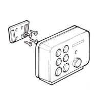
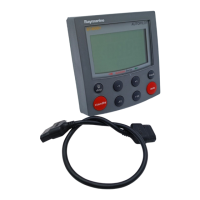
Details on siting, mounting, and connecting the control head unit.
Connecting the dedicated power supply for the autopilot.
Information on connecting spade connectors for electrical connections.
Connecting the ST4000 to the SeaTalk bus for data communication.
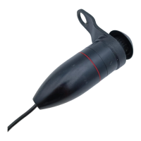
Information on mounting and positioning the fluxgate compass.
Guidance on optimal placement of the fluxgate compass.
Details on installing a rudder reference transducer for rudder angle readout.
Instructions for mounting the rudder reference unit.
Critical dimensions for tiller arm and rudder reference arm alignment.
Cabling connections for the rudder reference transducer.
Mounting and installation of the linear drive unit.
Alternative mounting for the drive unit on the port side.
Direct mounting of the ST4000 onto the starboard cockpit seat.
Steps for installing the tiller pin using epoxy.
Installing the mounting socket for the drive unit.
Overview of accessories for non-standard installations.
Using pushrod extensions to adjust length.
Using tiller brackets to vary tiller pin offset.
Attaching the autopilot to a vertical face using a cantilever socket.
Using a pedestal socket assembly to raise the drive unit mounting socket.
Connecting the actuator to the control head via plug and socket.
Assembling and installing the socket for the actuator cable.
Cabling for the NMEA data port.
Transmitting NMEA information to other equipment using a SeaTalk Interface.
Simple tests to confirm system wiring and setup.
Initial check upon switching on the autopilot system.
Checking the direction of helm application for course changes.
Verifying rudder reference transducer cabling and phase.
Checking the interface with position transducers via NMEA data port.
Checking the interface with a wind instrument via NMEA data port.
Performing an initial sea trial to fine-tune the autopilot settings.
Correcting fluxgate compass deviation for optimal autopilot performance.
Familiarizing with autopilot operation through manual steering and course changes.
Procedure to reverse the autopilot's operating sense.
Remote control units for autopilot operation at various positions.
Components for interfacing with wind, data, and rudder position sensors.
Maintenance advice for the control head unit.
Maintenance advice for the drive unit.
Maintenance advice for cables.
| Type | Autopilot |
|---|---|
| Display | LCD |
| Heading Sensor | Fluxgate Compass |
| Voltage | 12V |
| Course Computer | Integrated |
| Storage Temperature | -20°C to +70°C |