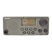
Page: 5 of 8
ALIGNMENT PROCDDURES
This transceiver is completely aligned at the factory and does not require any adjustments for installation.
However it is considered as good practice to verify that none of the adjustments are changed.
Do not adjust any circuitry in this radiotelephone unless you understand the circuit operation and have
experience in adjusting radiotelephone. Tampering with the radiotelephone may upset the alignment and
lower its performance.
Test Equipment Required:
!"
Regulated DC power supply, 10 -16V adjustable, 7A
!"
Audio signal generator, 10Hz~3kHz
!"
Digital multimeter
!"
Deviation meter {linear detector}
!"
Frequency counter, 0~500MHz high impedance
!"
Oscilloscope
!"
RF power meter,
≥
30W
!"
High frequency standard generator, >500MHz
!"
Tracking generator, >500MHz
!"
Distortion analyzer
!"
Audio level meter
!"
T-coupler
!"
Sinad meter
!"
Alignment drivers, etc.
!"
Or a radio communication test set 2955 (MARCONI INSTRUMENTS)
 Loading...