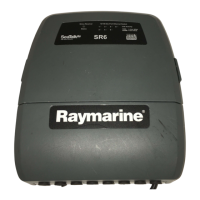
3.5Powerconnection
TheSR6canbeconnectedtoaDCpowersupplyof12or24V.
ThereisnopowerswitchontheSR6Siriusweatherreceiver,it
automaticallyturnsonwhenthesystemispowered.
Thepowerconnectionforyoursystemshouldbemadeateitherthe
outputofthebatteryisolatorswitch,orataDCpowerdistribution
panel.Thepowermustbefeddirectlytothesystemthroughitsown
dedicatedcablesystemandMUSTbeprotectedbyathermalcircuit
breakerorfuse,installedclosetothepowerconnection.
A2m(6.6ft)cableishard-wiredintotheSR6receiverfor
connectionasfollows:
1Red
12/24VBattery+ve
2Black0VBattery-ve
3
Drain/ground
Thiscablemaybeextendedtoadistanceof20m(60ft)using
suitablewire,gaugeAWG12orgreater.
Groundingrequirements
ThesegroundingrequirementsareapplicableforRaymarine
equipmentsuppliedwithaseparatedrainwireorscreen.
•Theproductpowercabledrainconductor(screen)mustbe
connectedtoacommongroundpoint.
•Itisrecommendedthatthecommongroundpointisabonded
ground,i.e.withthegroundpointconnectedtobatterynegative,
andsituatedascloseaspossibletothebatterynegativeterminal.
Ifabondedgroundsystemisnotpossible,anon-bondedRF
groundmaybeused.
Bondedgroundsystem(preferred)
 Loading...