33
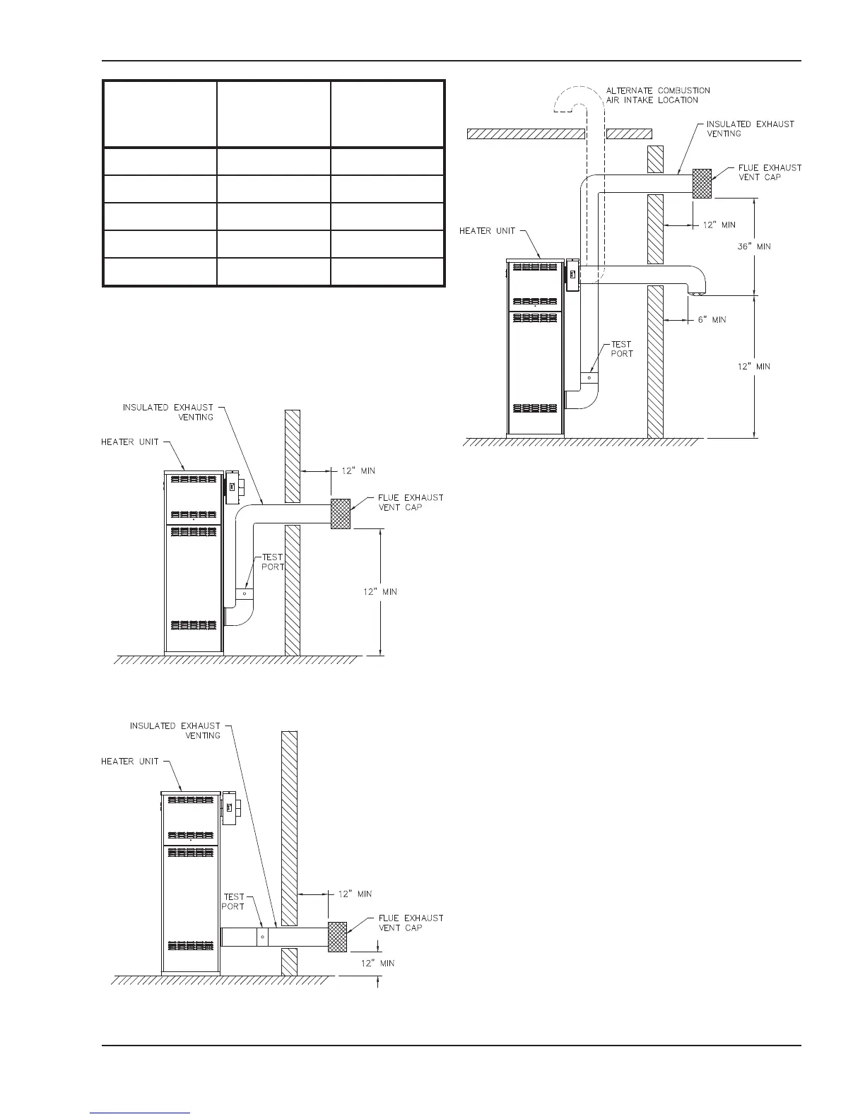
Fig. 33: Horizontal Through-the-Wall Venting
Fig. 34: Alt. Horizontal Through-the-Wall Venting
Fig. 35: Horizontal Through-the-Wall Direct Venting
Installation
These installations utilize the heater-mounted blower
to vent the combustion products to the outdoors.
Combustion air is taken from inside the room and the
vent is installed horizontally through the wall to the out-
doors. Adequate combustion and ventilation air must
be supplied to the equipment room in accordance with
the NFGC (U.S.) or B149 (Canada).
The total length of the horizontal through-the-wall flue
system should not exceed 75 equivalent ft in length. If
horizontal run exceeds 75 equivalent ft, an appropri-
ately sized variable-speed extractor must be used.
Each elbow used is equal to 10 ft of straight pipe. This
will allow installation in one of the four following
arrangements:
• 75’ of straight flue pipe
• 65’ of straight flue pipe and one elbow
• 55’ of straight flue pipe and two elbows
• 45’ of straight pipe and three elbows
The vent cap is not considered in the overall length of
the venting system.
When installing multiple sidewall vent terminations, fol-
low guidelines in fig. 30.
Horizontal Through-the-Wall Direct
Venting (Category III)
NOTE: Data for 100% firing rate.
Table M: Typical Volume of Flue Products
Model
No.
Vent Size
(in.)
V
olume of
Flue Products
(
CFM)
504A 8 170
7
54A
1
0
2
60
1104A 10 380
1504A 12 510
2004A 14 680