34
The vent must be installed to prevent flue gas leakage.
Care must be taken during assembly to ensure that all
joints are sealed properly and are airtight. The vent
must be installed to prevent the potential accumulation
of condensate in the vent pipes. It is required that:
1. The vent must be installed with a condensate
drain located in proximity to the heater as directed
by the vent manufacturer.
2. The vent must be installed with a slight upward
slope of not less than 1/4 inch per foot of horizon-
tal run to the vent terminal.
3. The vent must be double wall or insulated through
the length of the horizontal run.
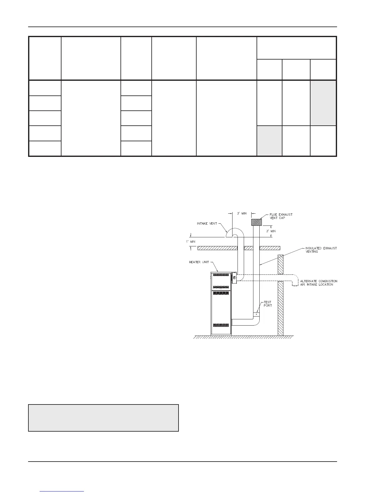
Termination
The flue direct vent cap MUST be mounted on the ex-
terior of the building. The direct vent cap cannot be
installed in a well or below grade. The direct vent cap
must be installed at least 1 ft above ground level and
above normal snow levels. The Raypak-approved
stainless steel flue direct vent cap must be used
(sales order option D-15). The vent terminal must be
located NO CLOSER than 12” off the wall.
Direct Vent—Vertical
Installation
These installations utilize the heater-mounted blower
to draw combustion air from outdoors and vent com-
bustion products to the outdoors.
The total length of air supply pipe cannot exceed the
distances listed in Tables L and N. Each elbow used is
equal to 10 ft of straight pipe. This will allow installation
in any arrangement that does not exceed the lengths
shown in Tables L and N.
WARNING: No substitutions of flue pipe or vent
cap material are allowed. Such substitutions would
jeopardize the safety and health of inhabitants.
Fig. 36: Direct Vent - Vertical
** Subtract 10 ft per elbow. Max. 4 elbows.
t
Adapters supplied by others.
Table N: Category III Horizontal Vent & Horizontal Direct Vent
Model
No.
Certified
Vent
Material
Vent
Size
(in.)
M
aximum
Horizontal
Vent Length
(
ft)**
Combustion Air
Intake Pipe
Material
Air Inlet
M
ax. Length** (ft)
6” Ø 8” Ø 10” Ø
504A
Category III
8
75
Galvanized Steel,
PVC,
ABS,
CPVC
45
100
t
754A 10
1104A 10
1504A 12
45
85
t
2004A 14