7
(ANSI Z223.1/NFPA 54).
The “two-opening” method requires:
1. Free combustion air 1 sq. in. per 1000 BTU input
within 12” of the floor.
2. Free ventilation air 1 sq. in. per 1000 BTU input
within 12” of the ceiling level.
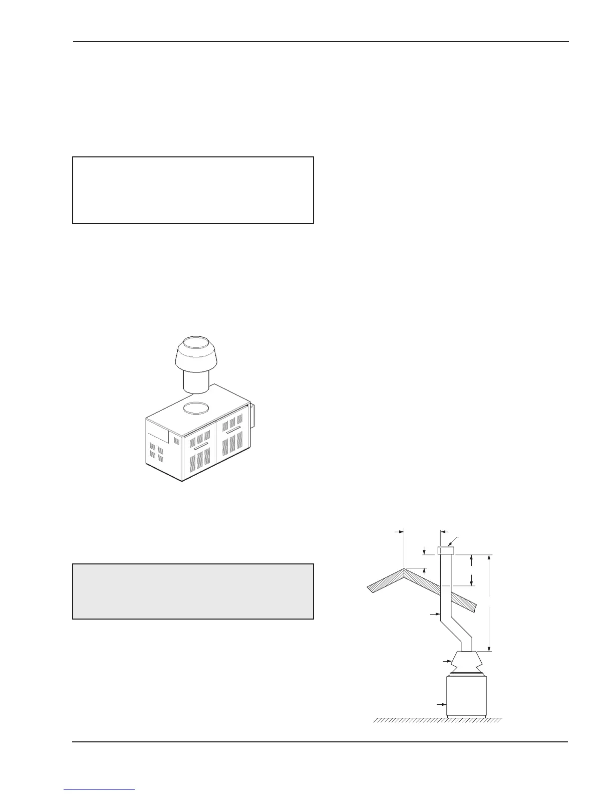
Venting Connections
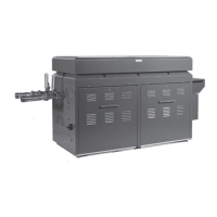
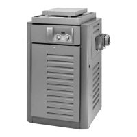
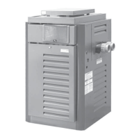
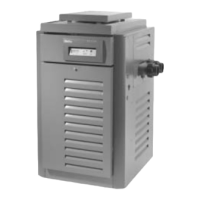
Drafthood (Indoor) Models 962-1826
Locate and assemble as shown in Fig. 3. Secure with
screws supplied in envelope in carton. Do not modify
the drafthood. The height of the relief openings above
the cabinet is critical to proper operation.
Models 2100-4001 have built-in drafthoods that must
be properly vented to the outside.
Vent Piping
Vent piping the same size or larger than the drafthood
outlet is recommended, however, when the total vent
height is at least ten (10) feet (drafthood relief opening
to vent terminal), the vent pipe size may be reduced
as specified in the National Fuel Gas Code, ANSI
Z223.1/NFPA 54 - latest edition. Avoid long horizontal
runs of vent pipe and too many elbows. If installa-
tion requires horizontal or non-vertical runs, the vent
pipe must have a minimum of 1/4 inch per foot rise
and should be supported at not more than five foot
intervals. Plumber’s tape, criss-crossed, will serve to
space both horizontal and vertical piping.
Gas vents supported only by the flashing and extend-
ing above the roof more than five feet should be
securely guyed or braced to withstand snow and wind
loads. We recommend use of insulated vent pipe
spacer through the roofs and walls.
For protection against rain or blockage by snow, the
vent pipe must terminate with a vent cap which com-
plies with the local codes or, in the absence of such
codes, to the latest edition of the National Fuel Gas
Code, ANSI Z223.1/NFPA 54.
The discharge opening must be a minimum of two feet
vertically from the roof surface and at least two feet
higher than any part of the building within ten feet.
Vent stack shall be at least five feet in vertical height
above the drafthood outlet. The vent cap location shall
have a minimum clearance of 4 feet horizontally from,
and in no case above or below, unless a 4-foot hor-
izontal distance is maintained, from electric meters,
gas meters regulators and relief equipment.
The weight of the vent stack or chimney must not rest
on heater drafthood. Support must be provided in
compliance with applicable codes. The heater top
and drafthood must be readily removable for mainte-
nance and inspection. Vent pipe should be adequately
supported to maintain proper clearances from com-
bustible construction.
Type “B” double-wall or equivalent vent pipe, certified
for Category I conditions, is recommended. However,
single-wall metal vent pipe may be used as specified
in the latest edition of the National Fuel Gas Code
ANSI Z223.1/NFPA 54.
NOTE: If the room the heater is installed in is
located against an outside wall and air openings
communicate directly with the outdoors, the openings
may be 1/4 the size specified above (ANSI Z223.1/
NFPA 54, latest edition)
Fig. 3: Indoor Drafthood
WARNING: An indoor heater requires a drafthood
that must be connected to a vent pipe and properly
vented to the outside. Failure to follow this procedure
can cause fire or fatal carbon monoxide poisoning.
5' MIN
2' MIN
10' OR LESS
2' MIN
VENT CAP
VENT PIPE
DRAFT HOOD
HEATER
Fig. 4: Venting Clearances
 Loading...