34 Thermalert GP Series Operator’s Manual
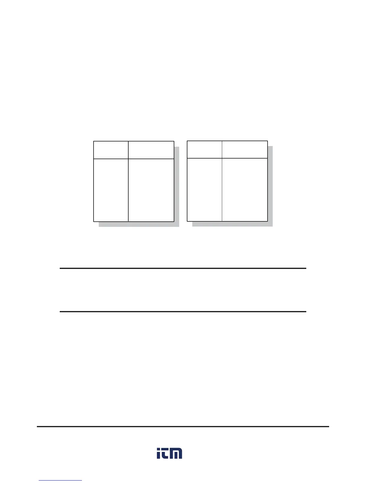
Thermalert GPR/GPS
Thermalert GPM
6
7
8
9
10
Black
Green
Bare
Red
White
TERMINAL
NUMBER
WIRE COLOR
4
5
6
7
8
Green
Yellow
White
Brown
Bare
TERMINAL
NUMBER
WIRE COLOR
Table B-2: Wiring GPR/GPS and GPM Sensing Heads
B.2 CONNECTING SENSOR HEADS AND INPUT DEVICES
Table B-2 shows wiring connections for the GPR/GPS and GPM sensing
heads to the monitor.
For wiring connections for sensing heads or other input devices with 0 to 5
volt and 4 to 20 mA outputs to the monitor, refer to Section 2.3.2.
WARNING
Incorrect wiring can damage the monitor, sensor, and/or input
device and void the warranty.

 Loading...