nne
co
er tu
e gas
o
ers
water
eaters –
o
er
anua
14
Relief Valve
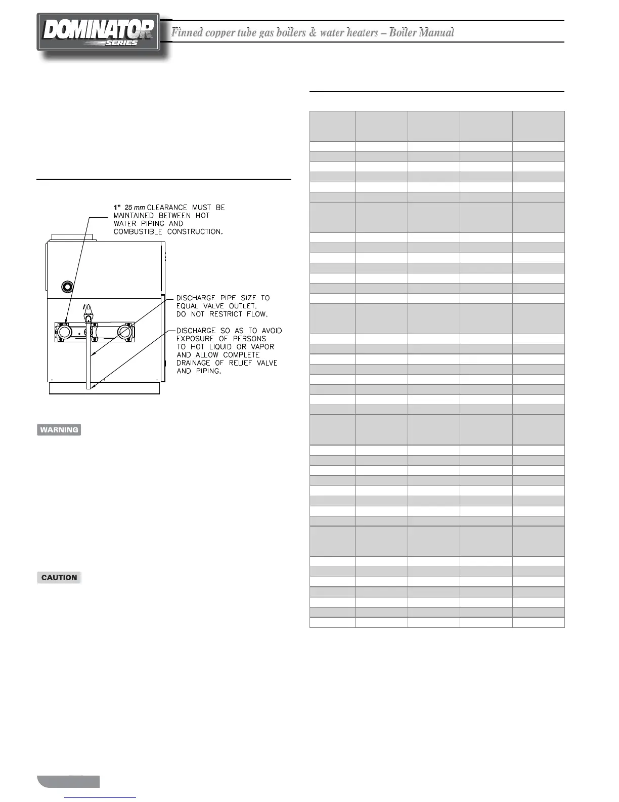
Pipe the discharge of the pressure relief valve to prevent scalding in
the event of a discharge, see Figure 10. e discharge piping must be
sized the same as the pressure relief valve outlet and installed to allow
complete drainage of both the relief valve and the discharge piping.
Figure 10 Relief Valve Piping
Never install any type of valve between the boiler/
water heater and the relief valve or an explosion causing
extensive property damage, severe personal injury or
death may occur!
Flow Switch
e ow switch supplied with the boiler/water heater must be wired
to the terminal strip in the control panel to prevent the boiler from
ring unless there’s adequate water ow through the unit. e ow
switch must be installed in the supply piping adjacent to the boiler
outlet connection.
Failure to properly install the ow switch may result
in damage to the boiler/water heater heat exchanger
voiding the warranty!
Table 7 Temperature Rise Table
ΔT = 15°F
ΔT = 8.3°C
Model
Flow Rate Pres. Drop
Flow Rate Pres. Drop
Number
GPM Ft
L/s kPa
300
34.0 0.22
2.1 0.6
400
45.4 0.49
2.9 1.5
600
68.1 1.30
4.3 3.8
750
85.1 2.35
5.4 6.9
900
102.1 3.84
6.4 11.3
1050
119.1* 6.23
7.5 18.4
ΔT = 20°F
ΔT = 11.1°C
Model
Flow Rate Pres. Drop
Flow Rate Pres. Drop
Number
GPM Ft
L/s kPa
500
34.8 0.36
2.2 1.1
750
52.2 1.08
3.3 3.2
1000
69.6 2.37
4.4 7.0
1250
87.0 1.46
5.5 4.3
1500
104.4 2.46
6.6 7.3
1750
121.8 3.84
7.7 11.3
2000
139.2 5.63
8.8 16.6
ΔT = 25°F
ΔT = 13.9°C
Model
Flow Rate Pres. Drop
Flow Rate Pres. Drop
Number
GPM Ft
L/s kPa
300
43.4 0.09
1.3 0.3
400
58.2* 0.19
1.7 0.6
600
72.8 0.51
2.6 1.5
750
87.1 0.91
3.2 2.7
900 101.3
1.49
3.9 4.4
1500
116.5 2.42
4.5 7.1
1350
91.9 4.74
5.8 14.0
1500
102.1 6.31
6.4 18.6
ΔT = 30°F
ΔT = 16.7°C
Model
Flow Rate Pres. Drop
Flow Rate Pres. Drop
Number
GPM Ft
L/s kPa
600
34.0 0.36
2.1 1.1
750
42.6 0.65
2.7 1.9
900
51.1 1.06
3.2 3.1
1050
59.6 1.73
3.8 5.1
1350
76.6 3.38
4.8 10.0
1500
85.1 4.50
5.4 13.3
1950
110.6* 9.20
7.0 27.1
2100
119.1* 11.27
7.5 33.2
ΔT = 35°F
ΔT = 19.4°C
Model
Flow Rate Pres. Drop
Flow Rate Pres. Drop
Number
GPM Ft
L/s kPa
750
36.5 0.49
2.3 1.4
900
43.8 0.80
2.8 2.4
1050
51.1 1.30
3.2 3.8
1350
65.6 2.54
4.1 7.5
1500
72.9 3.38
4.6 10.0
1950
94.8 6.91
6.0 20.4
2100
102.1 8.47
6.4 25.0
*Flow exceeds recommended maximum use a greater temperature
rise or consult manufacturer. Cupro-nickel heat exchanger should be
n
i
r
.

 Loading...


