nne
co
er tu
e gas
o
ers
water
eaters –
o
er
anua
25
On the four stage units, the le low re and high re switches
will interrupt power to the control module under a blocked ue or
inlet condition. is will cause the pilot and le and right main gas
valves to close. e right switches will only shut down the right main
gas valve under a blocked ue or inlet condition. e relay board
automatically selects between pressure switches as the boiler/water
heater changes stages. Tables 15 and 16 identify how pressure switch
control changes during boiler/water heater staging. Tables 17 and 18
identify the control actions if a low air condition occurs at any stage.
For example, when operating at stage 2, the le and right low re
pressure switches monitor the boiler/water heater, since the blowers
are operating at low speed. When the unit stages to stage 3 the le
blower will be switched to high speed and the relay board will switch
the circuit so that the le high re switch monitors the di erential
pressure for the le side. e right low re pressure switch will
continue to control the right side until the unit stages to stage 4.
At that point, the right high re pressure switch will automatically
take over monitoring duties for the right side. A low air condition
in either plenum will cause a red light to illuminate on the indicator
board.
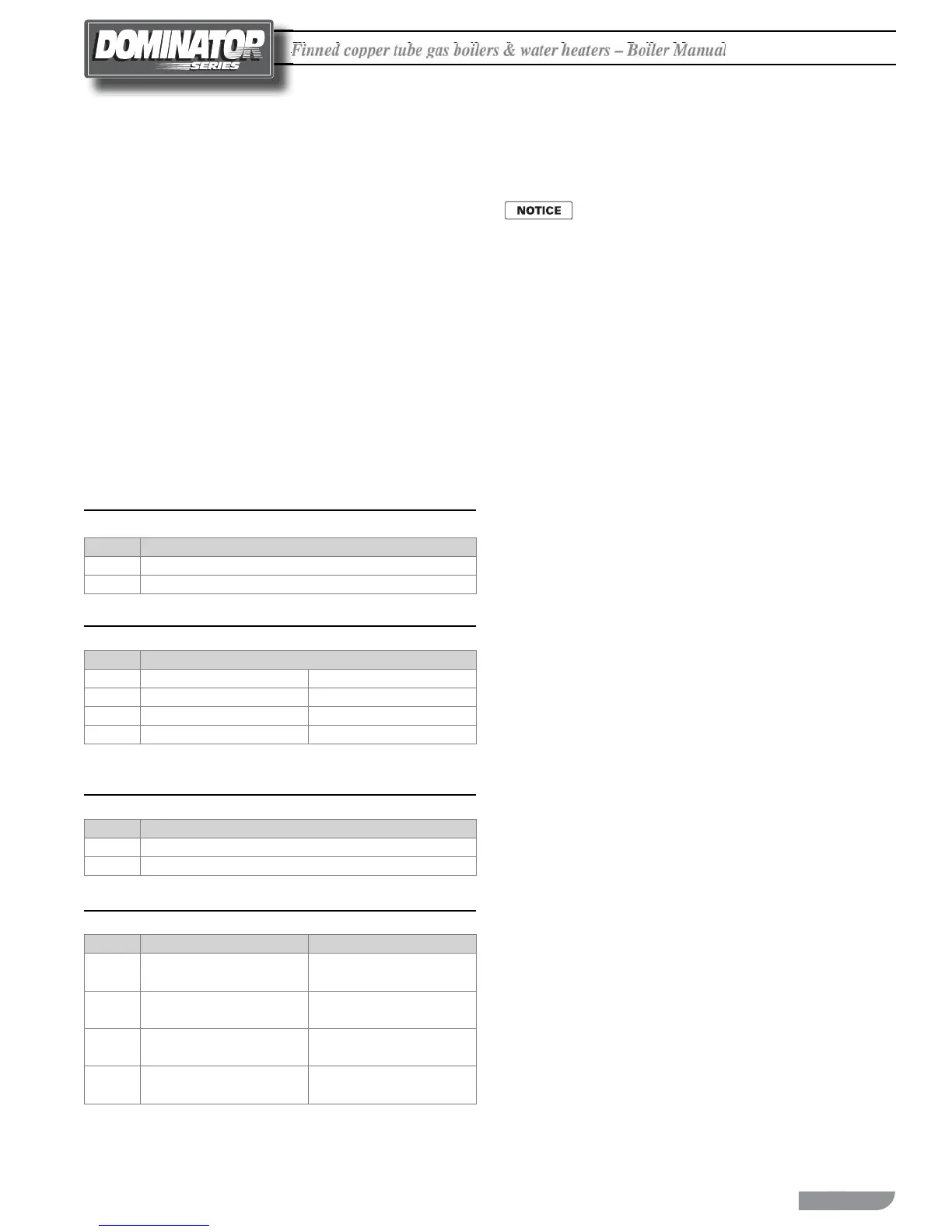
Table 15 Pressure Switch Control, D300-D2100
Stage Pressure Switch Mode
1 Low Fire
2 High Fire
Table 16 Pressure Switch Control, D1050-D2100
Stage Pressure Switch Mode
1 Left Low Fire N/A
1
2 Left Low Fire Right Low Fire
3 Left High Fire Right Low Fire
4 Left High Fire Right High Fire
1- At Stage 1, the right main valve will be energized.
Table 17 Low Air Condition Action, D300-D2100
Stage Control Action
1 No Power to Ignition Mode
2 No Power to Ignition Mode
Table 18 Low Air Condition Action, D1050-D2100
Stage Left Side Right Side
1
No Power to
Ignition Module
N/A
2
No Power to
Ignition Module
No Power to
Right Valve
3
No Power to
Ignition Module
Low
Right Valve
4
No Power to
Ignition Module
High
Right Valve
OPERATION SEQUENCE, 2 STAGE
D300 THROUGH D900
On Models D1050-2100, 2 stage, factory jumpers are
installed on remote staging terminal strip to force 2
stage operation. Refer to the included connection and
wiring diagrams for further control system information.
POWER ON:
Demand for Heat:
1. BTC staging control starts pump and begins 50 second delay
before energizing Stage 1.
2. Stage switch 1 closes.
3. System checks primary limit and other interlocks. Will not start
if either switch is open.
Prepurge:
1. TDR1 energizes starting a 40 second prepurge cycle.
2. K3 energizes the low speed side of the blower. If the side wall
vent option is used the power venter is energized, closing the
power venter interlock. e power vent indicator light illuminates.
3. e low air indicator light will remain lit until the blower comes
up to speed. e indicator light will turn o and prepurge
indicator light will illuminate when the pressure switches make.
4. At the end of the prepurge cycle TDR1 times out. K3 opens
and the prepurge indicator light goes out. K2 closes sending
24V ac to the ignition control.
5. K2 will switch the pilot valve, main valve and blower to the
high or low re mode, depending on the staging control input.
Ignition Trial:
1. Once energized, the ame sense module (FSM) initiates 4 second
diagnostic cycle before sending 24V ac to the PV terminal and
energizing the ignition transformer.
2. e ame failure LED will be lit during the 4 second diagnostic
cycle unless the unit is con gured for CSD-1. When the PV
terminal energizes, the LED will turn o . If the ignition trial
fails, the LED will relight.
3. e pilot valve and ignition transformer are energized for the
10 second ignition trial. e pilot indicator light illuminates
during this time.
4. If the ignition a empt is unsuccessful, the ignition module will
retry in 5 minutes.
5. Since the staging controller remains powered, it will continue
to stage up for as long as the call for heat exists. e blower,
pump and power venter will remain for as long as a call for heat
exists.

 Loading...


