nne
co
er tu
e gas
o
ers
water
eaters –
o
er
anua
24
BOILER/WATER HEATER OPERATION
Staging Operation
e Dominator boiler/water heater series is separated into 2-stage
and 4-stage units depending on the model size. e 300 through 2100
models have two ring inputs. e 1050 through 2100 have four.
Input staging is controlled from the staging controller that signals the
relay board to select the blower and gas valve modes. Table 12
identi es the stages and ring modes associated with the 2 stage units
(D300-D2100), and Table 13 identi es the stages and ring modes
associated with the 4 stage units (D1050-D2100).
Table 12 Firing Modes (D300-D2100)
Stage Left Firing Mode
Off Off
1 Low Fire
2 High Fire
Table 13 Firing Modes (D1050-D2100)
Stage Left Firing Mode Right Firing Mode
Off Off Off
1 Low Fire Off
1
2 Low Fire Low Fire
3 High Fire Low Fire
4 High Fire High Fire
1- The left main valve will operate at low fi re, but left and right
blowers will be on and operating at low fi re (low speed).
e outlet water temperature is automatically controlled by the
staging controller. It utilizes inputs from the inlet and outlet water
temperature sensors, plus optional tank and outside sensors, to stage
the boiler/water heater. e Dominator will stage up or down
progressively, but will not jump over a stage. Stage 1 will operate rst,
last and whenever the boiler/water heater is in operation. Consult
the staging controller documentation for further information on
controller operation.
For the D1050-D2100, the air inlet plenum is divided into
le and right sides. A separate blower, main gas valve and manifold
are used for each side. However, the combustion chamber is
undivided. For best overall performance, gas and air ows should be
balanced so that when both sides are at low or high re, stage 2 or 4,
the gas and air ows are equal.
Pressure Switch Settings
Di erential pressure switches are provided in the Dominator to shut
down gas ow under a blocked ue or inlet condition. One low re
and one high re pressure switch are used for the 300 through 900
models. Two low re and two high re pressure switches are used
for the 1050 through 2100 models. e low re pressure switches
serve to shut down gas ow if there is a blocked ue or inlet condition
during low re operation. Similarly, the high re switches will shut
down gas ow if there is a blocked ue or inlet condition during high
re operation. e di erential pressure is taken between the
air plenum and the pressure inside one of the main burners.
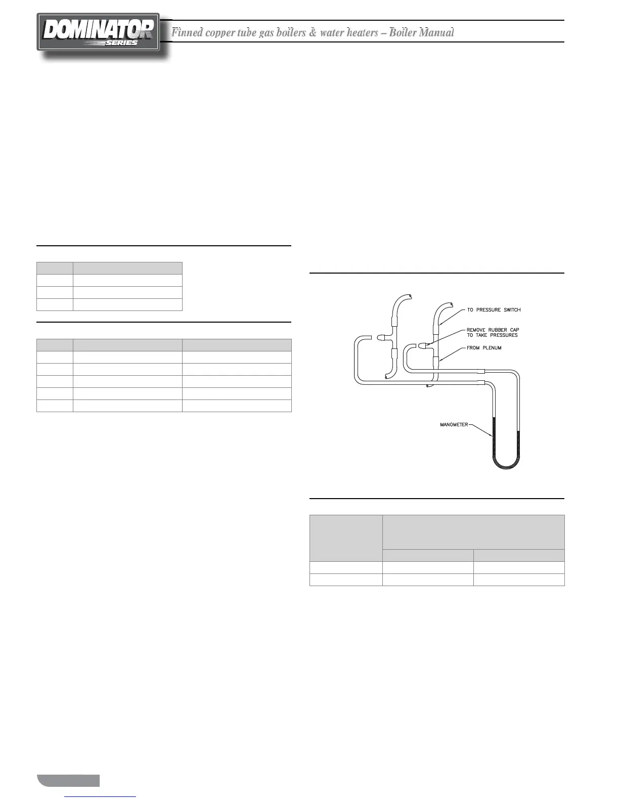
Pressure taps are provided in the control compartment for taking
the di erential pressure readings, Figure 17. Table 14 lists the
di erential pressure se ings for all of the models.
Figure 17 Pressure Switch Tap(s)
Table 14 Differential Pressure Settings (All Units)
Model
Differential Pressure
Requirement at High Fire
(All Units)
Inches W.C.
mm W.C.
300-900
1.0 ± 0.1
20.3 ± 2.5
1050-2100
1.0 ± 0.1
25.4 ± 2.5

 Loading...


