nne
co
er tu
e gas
o
ers
water
eaters –
o
er
anua
35
Figure 21 Heat Exchanger Upper Rail Screws
Vent System
oroughly inspect the vent system for any signs of blockage,
corrosion or leakage. Immediately replace any unsound vent system
piping.
Controls
Use the "BOILER/WATER HEATER OPE TION" and
"CHECKING AND ADJUSTMENTS" sections of this manual
for reference.
1. Check the thermostat or operating controls for proper operation.
2. oat type low water cuto device must be ushed out per the
manufacturers' instructions. e probe on a probe low water
cut o must be removed, cleaned and inspected at least once
a year. Ensure that the low water cuto s operate properly. If not,
replace them.
3. e ow switch contacts must be open when water ow is not
present.
4. e relief valve should not weep or discharge water at normal
system pressure. If it does, contact a quali ed service technician
to have it inspected. NEVER try to clean or repair the relief
valve! If the valve fails to operate properly, have it replaced!
5. e aquastat high limit controls the maximum water
temperature in the boiler. It should be set at least 20°F, 11°C
above the operator setpoint. If the water temperature reaches the
set temperature before the demand for heat has been met, the
aquastat high limit should shut the boiler o . e water
temperature should never exceed the maximum set point of
240°F, 116 °C. e aquastat high limit cannot be repaired. If
it fails to function properly replace it.
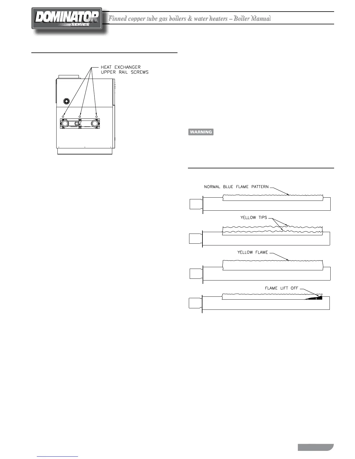
6. Visually check the pilot and main burner ames to ensure proper
operation, see Figure 22.
A yellow, oating ame indicates a lack of combus-
tion air. A li ing ame indicates too much combustion
air. Do not operate the boiler/water heater until the
problem is solved or severe personal injury or death
may occur!
Figure 22 Pilot and Main Burner Flame

 Loading...


