nne
co
er tu
e gas
o
ers
water
eaters –
o
er
anua
34
8. If there are no signs of damage, sooting or corrosion reassemble
the unit following the previous steps in reverse order.
9. A badly corroded or damaged heat exchanger must be replaced,
see the Heat Exchanger Removal section.
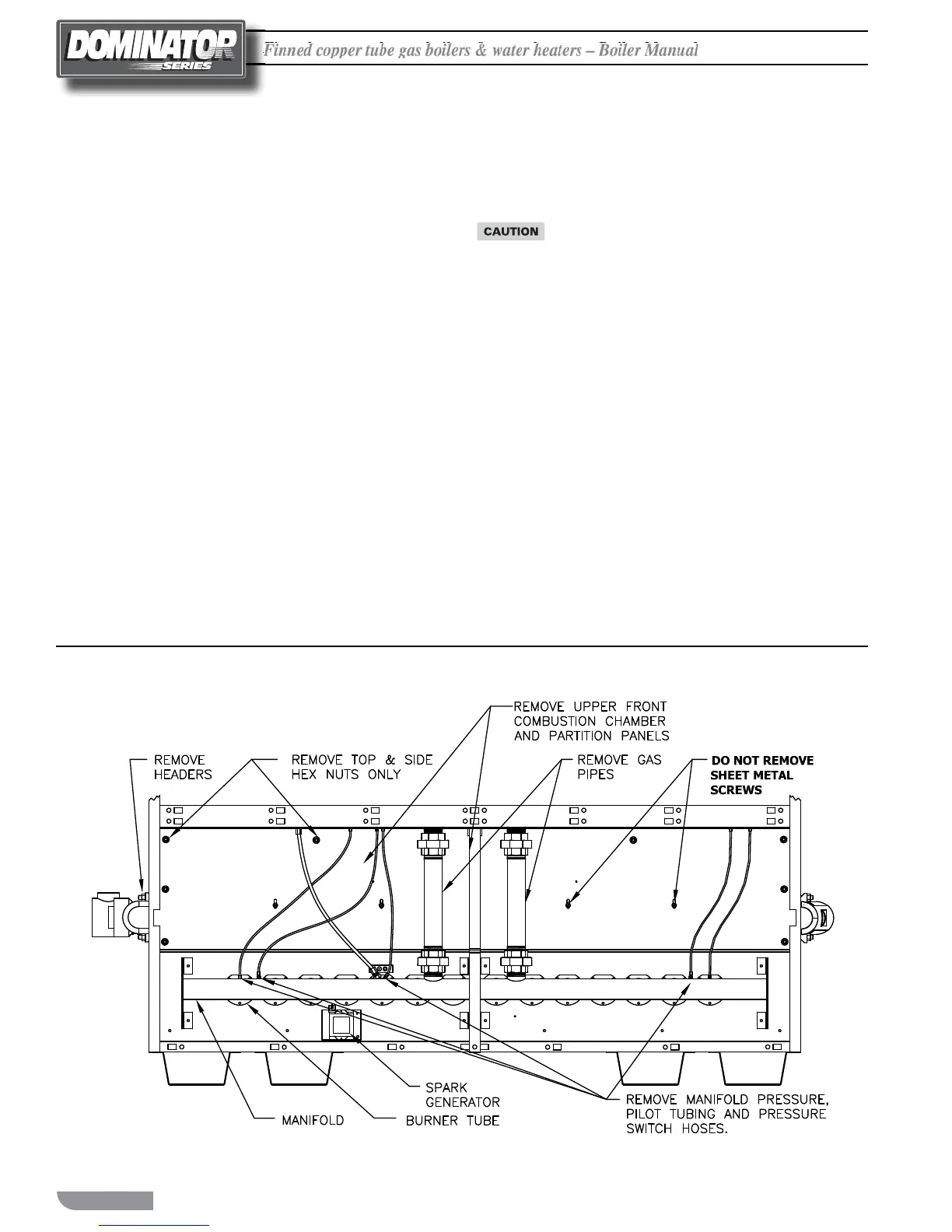
Heat Exchanger Removal, Cleaning
& Replacement - See Figure 20
1. Close the shut o valves in the inlet and outlet piping. On heating
systems close the system ll valve and relieve the system pressure
from the boiler by carefully li ing the relief valve or opening the
drain valve.
2. Drain the boiler/water heater and disconnect it from the system
piping.
3. Remove the inlet/outlet and return headers.
4. Remove the front jacket panels.
5. Loosen, 4 turns, but don't remove the 6 screws (3 on each side)
holding the heat exchanger upper rails in place, Figure 21.
6. Disconnect gas piping at the ground joint union(s). Also
disconnect the pressure sensing lines, pilot tubing and ignition
and sensing leads.
7. Remove the upper partition panel, 1050 thru 2100 models.
8. Remove the 1/4 inch nuts and washers holding the upper com-
bustion chamber front panel in place and carefully remove it.
9. Carefully slide the heat exchanger out of the unit.
10. Remove the "V" ba e straps and "V" ba es.
11. oroughly inspect the heat exchanger for signs of damage. If
there is no damage, clean the heat exchanger with water from a
high-pressure hose. Use a so bristle brush if necessary.
Never clean the heat exchanger while it’s in the boiler/
water heater or the combustion chamber will be
destroyed!
12. Sagging or distorted heat exchanger tubes are an indication of
low water ow through the system. A leaking or otherwise
damaged heat exchanger must be replaced and the condition that
caused the damage resolved before the boiler/water heater is
returned to service.
13. If the heat exchanger isn't damaged rewire the heat exchanger
ba es in place and slide the heat exchanger back into the unit.
14. Reinstall all of the other components in the reverse order of their
removal.
15. e torque values for the bolts that secure the removable headers
are 17-20 lbs. Once bolts have been started and secured the
tightening sequence is as follows:
1) Middle Top
2) Middle Bo om
3) Right Top
4) Le Bo om
5) Le Top
6) Right Bo om
Figure20 Burner and Heat Exchanger Servicing

 Loading...


