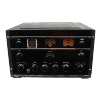
DIALS
The
Main Tuning Dial
is
on
the
left and consists
of a disc with seven scales, one for each of the
six
bands and a log scale.
The
Standard Broadcast Band
is
calibrated in kilocycles and the other
five
bands in
megacycles.
The Vernier Tuning Dial
is
in
the
center and has
a scale with arbitrary calibrations for exact tuning
and log records of
pttrticular communication stations.
It
is
used in conjunction with the log scale on the
main tuning dial to
give
additional figures for logging.
The
Tuning Meter
is
on the right and
is
calibrated
in DB's above one microvolt.
The
meter
is
used as a
tuning meter to indicate accuracy of tuning, and
also
gives an indication of the strength of the signal being
received.
CONTROLS
Power-Transmit-Receive Switch - This is a four,
position switch. Starting from fully counterdockwise
these positions are:
1.
Power
off.
2.
Transmit position which gives energized tube
fila\llents, open plate circuits, and shorted ter'
minals for transmitter relay on the speaker
terminal board on the back of
the
chassis.
Connect relay to these
two
terminals for
transmitter operation.
See
Figure
3.
3.
Normal reception.
4.
CW·
reception - Beat frequency oscillator
switched on.
Selectivity
Switch - This
is
a five' position switch
and the band widths and control
of
selectivity are
illustrated in the
curves of Figure
12.
The
five
posi,
tions
are:
1.
I-F band width for High Fidelity, modulated
_ reception.
2.
I-F band width for normal modulated recep'
tion.
3.
Crystal Filter
in-for
CW
telegraph or sharp
modulated signal reception.
4.
Crystal Filter in - for sharper
CW
telegraph
reception.
S.
Crystal Filter in - for sharpest
CW
telegraph
reception.
It
will
be noticed that when
tuningjn
a modulated
signal with the crystal in. the speaker volume
is
greater
on
either side of the point which gives the maximum
tuning meter indication.
The
reason for this
is
that
~e
carrier voltage controls the gain of the receiver
by
means
of
the
AVC
circuit, and
if
the carrier fre,
quency
is detuned slightly ftom resonance,
the
gain
of
the
receiver increases, so that part
of
the side band
frequencies are
amplified very much more'
than
they
are when the
carrier
is
tuned to exact resonance. This
is characteristic and normal for receivers with this
degree of selectivity which are provided with
AVC.
Care should be taken to tune the receiver for a maxi,
mum meter indication.
The
background noise and
ad-
jacent channel interference will thus be materially
reduced.
Noise Limiter-A
VC
Switch - This
is
a four·posi·
tion switch and starting from the fully counter clock,
wise position these are:
1.
AVC
and NL out - Manual gain only - for
CW
no interference.
2.
NL on,
AVC
out - Manual gain - for
CW
with interference.
3.
NL and A VC on - for Modulated Reception
with interference.
4. A
VC
on, NL out - for Modulated Reception
no interference.
R·F Gain
Control-
This continuously variable
sensitivity control
is
for use in conjunction with the
audio gain (Volume) control for all manual gain
op-
eration.
With
A
VC
on, it should
as
a rule be set
to
lis
fully clockwise position
Or
may be turned to elimi-
nate interference.
Experience with
thl..
operation of this control win
add to the values obtainable from the receiver.
Noise LinUter Control - This control sets
the
in~
strument for operation at the required percentage
value of Noise Limitation.
The
fully clockwise
posi~
tion limits the noise interference to 100% modulation.
As the knob
is
turned counterdockwise, the noise
in~
terference
is
limited to continuously lower percentages
of
modulation so that in the fully counterdockwise
position the Noise Limiter is operative on any modu-
lation whatsoever. Normally. the fully clockwise
posi-
tion will be used, but under extreme conditions
of
interference a balance point should be found for
maximum intelligibility of signal with best
modula-
tion and least noise.
Tone
ContrOl-
This
is
a continuously variable
control for reducing
HF
response. In the fully
clock~
wise position the full tone
is
,obtained and
as
turned
counterclockwise, high tones are lessened.
Set
it
to
suit the particular tonal conditions
forthe
signal being
received.
..'
.'
.
Beat
Frequency Oscillator Control - This control
is
normally used for
CW
code signals.
It
gives the re-
quired audio pitch after tuning, and usually should
be set slightly
off central position for the desired beat
frequency.