VI
INSTALLA
TION
Power Supply -
The
power supply circuit
is
in'
tegral with the receiver. Determine line voltage and
frequency and check with the rating
of
the receiver.
The
power transformer primary may
be
connected
for
anyone
of
five
voltage
r3:nges
by means
of
a tap
switch. This switch is located in the rear apron of the
receiver. and the voltage for which
it
is
set may be
read directly on the switch.
For Battery
or
other Supply Operation - For con'
nections see Schematic Diagram Figure
11.
It
is
only
necessary to remove the plug from the socket on
the
rear
of
the receiver, and connect the batteries
to
the
proper terminals
as indicated by the schematic dia'
gram. A battery cable terminating' in an octal male
plug
is
necessary for this purpose. A vibrator power
supply
MI,8319
is
available which will operate the
receiver directly from a 6 volt storage battery. For
information on this power unit
see
Section XI.
Tubes -
Inspect the chassis before applying power
to
see
that
all tubes are firmly seated in their respec'
tive sockets.
Antenna
- The input impedance
at
the antenna
terminals
is
designed to match a 200 ohm transmis'
sion line except on the
broadcast band where a low
frequency primary
is
used.
For general use it
is
recommended that a straight
wire antenna between
25
and m feet long be used.
Speaker Terminals for connection
of
a loud,
speaker are indicated in Figures
3 and
6.
The
output
transformer is designed to match a speaker having
2.25 ohms impedance.
Headphones - A jack
is
provided on
the
left
of
the front panel for plugging in a pair of headphones.
There are two positions
of
the plug.
1.
Half
way
in-for
reception on both speaker
and phones.
2.
Fully. in-=-for phone receptiori only.
See
"CIRCUIT
ARRANGEMENT"
"Output
Tube."
Mounting -
The
instrument may be placed on a
table
or
mounted on a rack.
ror
rack mounting loosen
the panel mounting screws and remove the front
panel and chassis complete from the cabinet.
Then
mount on rack by means of the slots
at
the
sideS
of
the panel.
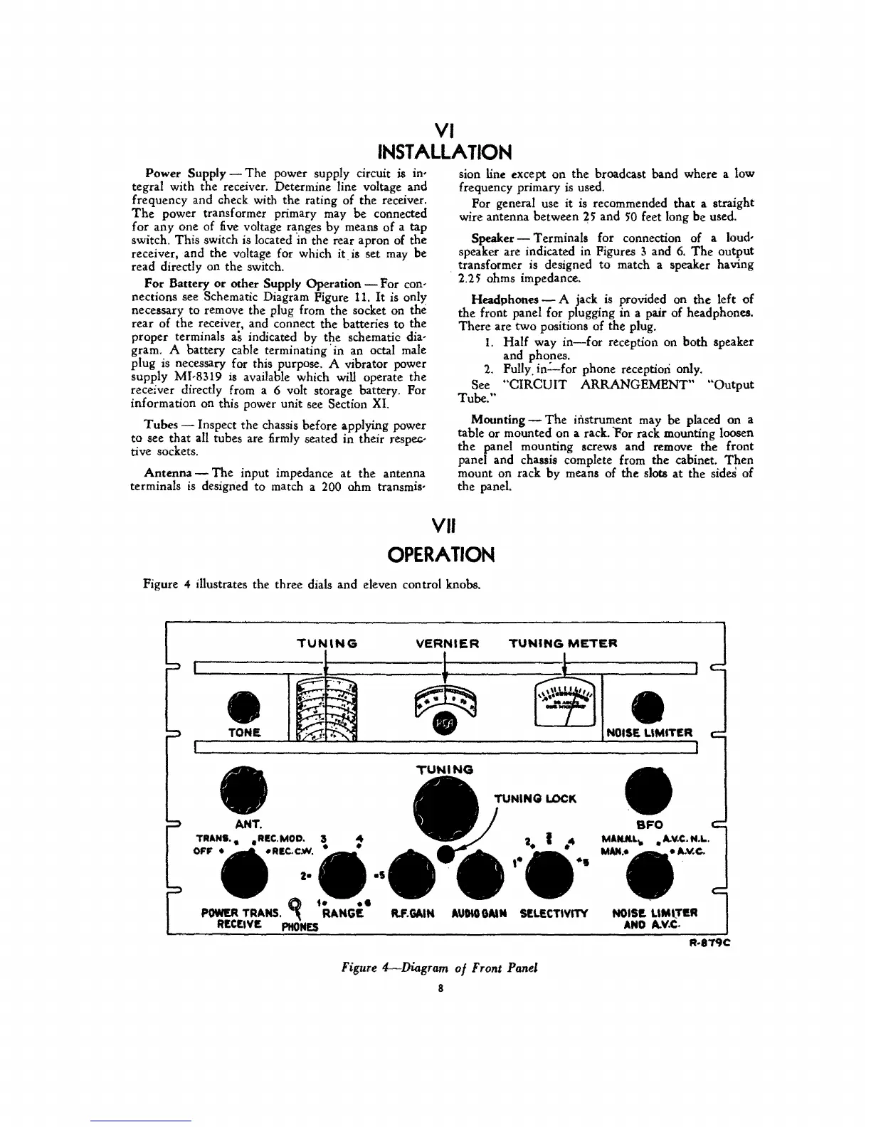
VII
OPERATION
Figure 4 illustrates the three dials and eleven con trol knobs.
TUN'NG
VERNIER
TUNING
METER
I
I
I
-*-
;;.-..-
-., .
.!
--~;
•
;......f!;"
~
\ \ \1
'"
,-'''''';
\..-.::.
I
~
.;...
ttII
..
~
.......
1 •
TONE.
~
;r;;~,
I
ANT.
TRANS.. .REe.MOD. 3
OFF
•
_REC-CloY.
•
•
;R
~
•
TUNING
M.GAIN
AUDIO
GAtM
SELECTIYITY
Figure
4-Diagram
of
Front Panel
8
J
I
•
NOISE
LlMIT£R
I
SFO
M1NJlU....
•
II..Y.e..
N.L.
MAN..
.1I..v.c.
NOIS!. LlMl.TI!.R
AND
A.V.C.
R-8T9C