GENERAL
PURPOSE
COMMUNICA
TlONS
RECEIVER
I
INTRODUCTION
In
the design of a high frequency radio receiver,
there are four important qualities for consideration:
1.
Usable sensitivity.
2. Selectivity.
3. Frequency Stability.
4. Reliability.
The
sensitivity of this receiver
is
limited only by
the tube noise originating in the first tube and its
asso-
ciated circuits. A large ·part·
of
this noise
is
due to
"shot" effect and thermal agitation in the first tuned
circuit. A signal, to be readable, must
produce a volt:
a&-e
on the grid,
of
the same or
greate~
ordet: of mag'
I1Lt!Jde
than this inherent noise voltage. Therefore, an
efficient coupling system between the antenna and the
first R,F tube of the receiver
is
of great importance.
This
has been the subject of considerable develop"
ment, and the system used on this receiver gives opti,
mum coupling with antenna or transmission line
im'
pedances
of
200
ohms, over the entire frequency
range of the receiver, except on the broadcast band.
On
the
broa~ast
band, a low frequency primary
is
used, resonating well below the band with a 200 mmf
antenna.
The
second quality of a receiver, selectivity, is
nec'
essarily a compromise with fidelity of the reproduced
signal. This receiver
is
designed
to
have
five
degrees
of selectivity, three of which include a crystal filter.'
1'0 secure good frequency stability, rugged con'
struction of parts and wiring in the high frequency
heterodyne oscillator circuit has been included in
the
design. This, together with voltage stabili2;ation of
the oscillator plate supply, temperature compensation,
and proper oscillator excitation, provides a high
de'
gree of stability.
Reliability depends
to
a large extent on the quality
of
material and workmanship. Throughout the AR,SS
Receiver the best material obtainable is used for each
particular purpose and
all
workmanship is of the best.
The
following instructions should be studied before
the installation or operation
of
this equipment is
at'
tempted, in order
that
optimum performance may
be
obtained.
11
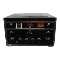
EQUIPMENT
The
equipment furnished consists of the Receiver
Chassis Assembly, including control panel and
tubes and cabinet for complete enclosure for table
mounting.
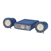
Additios:al equipment required includes headphones
or
loudspeakers, an antenna system, and an
AC
sourCe
of power, batteries,
or
Vibrator Power Supply
Unit
MI'8319.
III
DESCRIPTION
This receiver covers short wave, standard broad,
cast, and
r;:,w
service; its principal use
is
for short
wave. communications.
It
is designed
to
withstand
severe climatic and line voltage variations without
ap'
preciable impairment
of
performance.
Its features include: .
Mechanical Band
Spread with Single Control for
ease of tuning a previously logged station.
Automatic Noise Limiter which automatically
limits interference
to
a percentage of modula'
tion determined
by
the Noise Limiter Control.
Noise Limiter Control for setting Noise Limiter
to
operate at any desired percent modulation.
Noise Limiter
Switch for switching Noise Lim-
iter on
or
off.
Continuously variable
High
Prequency
Tone
Control.
$
nntenna
trimmer for circuit alignment.
Crystal filter for ultra'sharp selectivity when
re-
quired.
Tuning meter for indicating relative strength
of
incoming signals.
Exceptionally good oscillator stability through
normal variations in line voltage.
Pour'gang Condenser giving high image ratio
on
all
bands.
Twelve Tuned
I,P Circuits giving a very high
degrelllOf selectivity.
Temperature compensated oscillator circuits on
all bands.
Ceramic Insulation throughout on gang
conden-
ser, sockets, range switch, and selectivity
switch.
Tuning Lock for service under extreme condi,
tions of vibration.