IV
CIRCUIT
ARRANGEMENTS
The
circuit
is
shown schematically in Figure
1l.
It
consists of two stages of
R'F
amplification, first de'
tector,
first heterodyne oscillator; three stages of I,P
amplification, second detector, noise limiter, second
heterodyne oscillator;
A,
P amplifier stage. output
power
stage and power supply system.
Input Coupling -
The
antenna coupling. system is
designed
to
provide ,optimum coupling from a 200
ohm
transmission line. ,except in the broadcast band.
The
nrst tuned circuit
is
provided with a trimmer con'
denser adjustable from
the
front panel. This insures
for minimizing cross modulation and blocking effects
from strong iryterfering signals and for obtaining a
high degree
of
image signal suppression.
The
amplifi'
cation
is
adjusted
to
provide optimum signal.ta-noise
ratio by making noise contributions
of
circuits follow'
ing the first tube negligible in comparison with the
noise contributed
by
the first
R'P
grid circuit; that
is, each tuned circuit in the receiver contributes some
noise voltage.
but
by making the gain
of
the first tube
as
high
as
practicable, the noise contributed
by
suc'
ceeding circuits is unimportant.
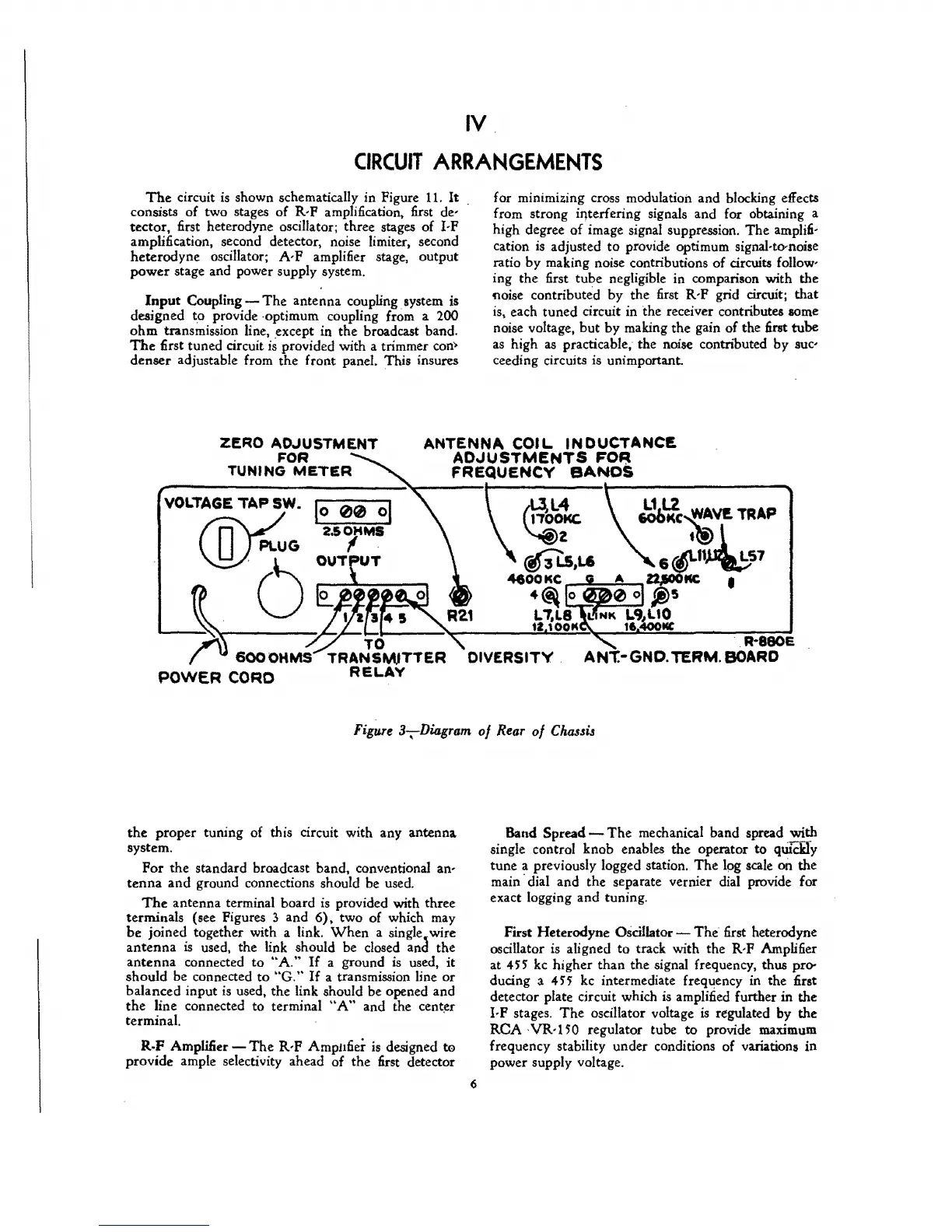
ZERO AD.JUSTMENT
FOR
TUNING
METER
ANTENNA
COIL
INDUCTANCE
ADJUSTMENTS
FO~
FREQUENCY
BANDS
VOLTAGE
TAP
SW. 1
0
00
01
Jc!o~-{~V!.
TRAP
friVO
PLUG
2.S
/
MS
tt!) l
\J::!)
~U
0 T T 6
~11~S7
~'~()-~~Tlo~~R~--~~~~--'~
~!
R-e80E
6000HMS
TRANSWTTER
DIVERSITY.
ANT.-GND. TERM.
BOARD
POWER
CORD
RELAY
Figure
3,Diagram
of
Rear
of
Chassu
the
proper tuning of this circuit with any antenna
system.
Por
the standard broadcast band, conventional an-
tenna
and
ground connections should be used.
The
antenna terminal board
is
provided with three
terminals (see Pigures 3 and
6),
two of which may
be
joined together with a link.
When
a single, wire
antenna
is
used. the link should be dosed and the
antenna
connected
to
"A."
If
a ground
is
used,
it
should be connected
to
"G,"
If
a transmission line
or
balanced input
is
used, the link should be opened and
the
line connected to terminal
"A"
and the center
terminal.
'
R.F
Amplifier -
The
R,P
AmpI1fier is designed
te
provide ample selectivity ahead of the first detector
6
Band Spread -
The
mechanical band spread with
single control knob enables the operator to
qwCHy
tune a previously logged station.
The
Ipg
scale
on
the
main'dial and the separate vernier dial provide for
exact logging and tuning.
First Heterodyne
Oscillator -
The
first heterodyne
oscillator
is
aligned
to
track with the R,P Amplifier
at
4H
kc
higher
than
the signal frequency, thus pro-
ducing a
45'5
kc
intermediate frequency in the first
detector plate circuit which
is
amplified further
in
the
I,P stages.
The
oscillator voltage
is
regulated by the
ReA
VR·150
regulator tube
to
provide maximum
frequency stability under conditions of variations
in
power supply voltage.