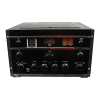
TUNING
For functions of controls see the foregoing para'
graphs.
1.
Turn
receiver on and set the Power' Transmit,
Receive Switch for the required type of
operation.
2.
Set Range Switch for band required.
3.
Set Antenna Trimmer for maximum back,
ground noise.
4
..
Set Selectivity Switch for the required oper'
ating conditions - See Selectivity
Curves-
Figure
12.
5'.
Set Noise Limiter-A
VC
Switch for the
re'
quired operating conditions.
6.
Set R,F Gain Control fully clockwise.
7.
Set Audio Gain Control about halfway
8.
Tune in the station.
9. Reset Audio Gain
Control to give deslred
volume.
10.
Reset Selectivity and Sensitivity (R,F Gain)
Controls and Noise Limiter Control
in
aC'
cordance with requirements due
to
inter'
ference, station transmission, and other 'con,
ditions.
11. Set Tone Control for preferred tone.
12.
On
CW
operation set Power·Transmit,Re'
ceive Switch
to
"Rec.
CW"
(position 4) and
set
BFO Control to give desired pitch.
13.
If
the receiver
is
subject to vibration, the tun-
ing may be locked by turning clockwise the
knurled screw directly beneath
the
tuning
knob.
Turning
the screw moderately tight
will lock
the
tuning.
Diversity Reception - Connect together the
ter-
minals marked "diversity," Pigure
3,
on two
or
three
of these receivers, and equip each receiver. with a
separate antenna.
The
"diversity" terminal is
con"
nected inside the receiver
to
the A
VC
circuits. Tune
as explained.
VIII
MAINTENANCE
This receiver should maintain its correct factory ad,
justments over a reasonably long period
of
time.
Causes of trouble and the probable sequence of their
development are outlined in the following paragraphs:
1.
Vacuum Tubes - A noticeable decrease in the
sensitivity of the receiver
us~ally
indicat~
worn
out vacuum tubes.
If
the sensitivity
is
low.
re'
move and check the
tubes'
in a reliable tube
tester or substitute new tubes one
at
a time.
See Technical Summary, and Schematic Dia'
gram Figure
11.
Tube socket voltages are given
in
Table
2.
2.
Range Switch - A switch may operate defec-
tively on certain positions after long periods
of
inoperation. Usually rotating
the
switch back
and forth several times will clean
the
contacts
and operation will become normal.
A bad
range' switch contact is likely
to
cause a
change in the sensitivity of the receiver, or the
frequency of a received signal, as
the
switch is
moved back and forth slightly in a certain fre,
quency band position. A further check
is
to
turn the switch off and on at one particular fre'
quency band several times apd note the
ap'
parent sensitivity of the receiver each time the
switch comes into position.
The
sensitivity
should be the same each time and may be
ade'
quately judged for this test by listening
to
the
receiver background noise.
3.
Automatic Volume Control
and
Tuning
Meter
-The
A
ve
voltage
is
obtained from
the
second
10
detector.
It
controls the first and second
R,P
and nrst and second I·P tubes.
The
tuning meter
is
connected in the cathode circuit of the 1st
I'P
tube and thus records changes
in
cathode
cur'
rent caused by changes
of
AVe
voltage applied
to the grid.
The
tuning meter should normally
give a low scale reading when
no
signal
is
being
received.
To
adjust this meter;fune the receiver
to a point
free
of
signals,
turn
the sensitivity
control
to
maximum, switch in
AVe,
switch
crystal
"Out,"
have antenna trimmer turned
off
resonance, and then adjust
the
potentiometer
R21
Jlt
the back of the receiver, as shown
in
Pigure
3,
until
the
meter pointer just coincides
with
the
mark
at
the low end
of
the
scale.
The
meter will ustlally rise slightly when the antenna
trimmer is tuned to resonance.
4. Circuit Alignment
Alignment
Tools - ,Special tools for align'
ment of
R,P
and I·P circuits are provided.
They
ate mounted in fuse clips on either side of the
gang condenser cover, and are available after
removing
the large R,P unit cover.
The
shorter
one of the
two
is
for adjustment
of
all R·P and
I·P coils, and the longer one
is
for adjustment
of the plunger type trimmers.
One
end
of
this
tool
is
for turning the lock
nut
on the trimmers
and the
oth~r
end has a hook for engaging in
the hole in
the
end of the plungers.
After
ad-
justment, the lock nut should be securely tight-
ened.