. i . i i n i
08
'
i,
/Ji.~~~5:t~H)
L42
-:r
- - -
--
_
11
_ 7 I C21-"'s BANO
(L41
BOTTOM)
\
~-..........
/~
22,'TDOKC
L4l
-::1----
-
110
1
"3
ItO
LF.
CI9-*zlWlo
L5l-.28AM~54-""8AHD
//;;
-[LSS-"SBANO
(L44BOTTOM)\
[~-r;'F.)
6SS1
..
'4'
.~KC
d/1570KC/
11,
90
°5/:'/
2'lOOOKC
L4S
-::J"
TR"~
R"NS
B.£OTRAKS
\.
l.!J
~
~
Gr
t!f/®---
rr
CI6
-.,
BANO
(LA'
BOTTOM)I
__
~6.F.O.
6J5
6SS1
CU®~'C'ZS"'''BANO
/
11
1600KC
LZ2.
-r
Si
TRANS
~=o
6J5
16))00
KC
At
~
-~
LSt-
*1
BANC
(0'"
TOP)
H6
lID
2110
~y
.
QJ
~
535
KC
L3b 6
i~~~J{?·F.tF~~n
1ST~'
51"'38AHO
$----
- - C32-*S8,ANO
CL3S6OTTDMlr-----
A"'S,
S
0""
6SA1
.450
KC
__
IT
3'Z,000KC
.
~ISE"
'"
.
<;...
- - "li-
H!---..)
6H6
LIMITED
......
?C6O''zBANO_
~C&+*4eA"O
t§)-r
~_
.JI
C6S-
M
e
BAND
\_
............
1"'"
_1),...00
<4)QO
-.....
Ci1"'
(6,400
KC
~
~.
-l31'!l
OO
KC
L'33
1_
-
P;-1:;~6SG1
.;:~~
~
Ug..
••
"W.DI~
......
'®o...
L'31-~BAND
(l,!2!BOTTOM)i'
~
_~
RA
/'
C!iI:
17.,100KC
~~"
'22,5DOI'\C
L'54
-J
1
_\6SJ
1J1U
~F.
f!l1.2516-
~";
6SG1
\ LZ'LZ
.....
,.Alto
.....
,',
'~I
'C59-·1
BAND
(OM
TOP)
~_
ia'BANo"
@
4600KC
~
@l~,
" I
1500
KC
--
1700
KC
_'~
~,-,
'\
,
PHASING
Tl.
UTPUT
LOAD
~SI
~
{li;1
C6Z""'BAN
r<iiil
'\
Cii!.
"$
LZ~L24-.,BANO
CONTROL
UT PUT
6K6
~_J!!!'l/
~"'l{
1t,500KC
.....
,
tiill'
\~
,60
KC
C3S.....................
°TRAHS
GT
(0~11
'i>
C41-"48ANO
IJ
\
..,.
'\
\,
LlO-"'s
BAN
D
tlt18AND_
__/.::::-i:so
\ I
6SG1
r
18
/
400
KC
j
I \ \ \
~\1S'400
KC
4300I<C
l~"""'-'::"'::[FILTER
/ I
L11,U8-
I \
\\
C66-*SBAND
L1t
CHOK",J
1
ST
R.F.,
*381\NO I " \
\\"
\'22,'500KC
-4
BAND
.,
......
...
4tOOl'lc. \
~
lt1DOKClI--------.....
--
_.-"~BANO
I I \ \
C37-'"
1
BAND
,-----
'1500KC
I
\1
!lOO
KC
IS
'6
-
Tt
J I \
~
t.ND
POWER
1 \
~
L'Zl-*'SBANO
1
700KC
TRAMS.
~
,
22,500KC
- I I " ,
U3-L14--1BAND
C45-¥s9AND
\ SOOKC
3\,SOOKC
\C43-"BAND
L'20-*'$BANO
2'1 0 .... c
'8,400
Kc:.
1\-88'9
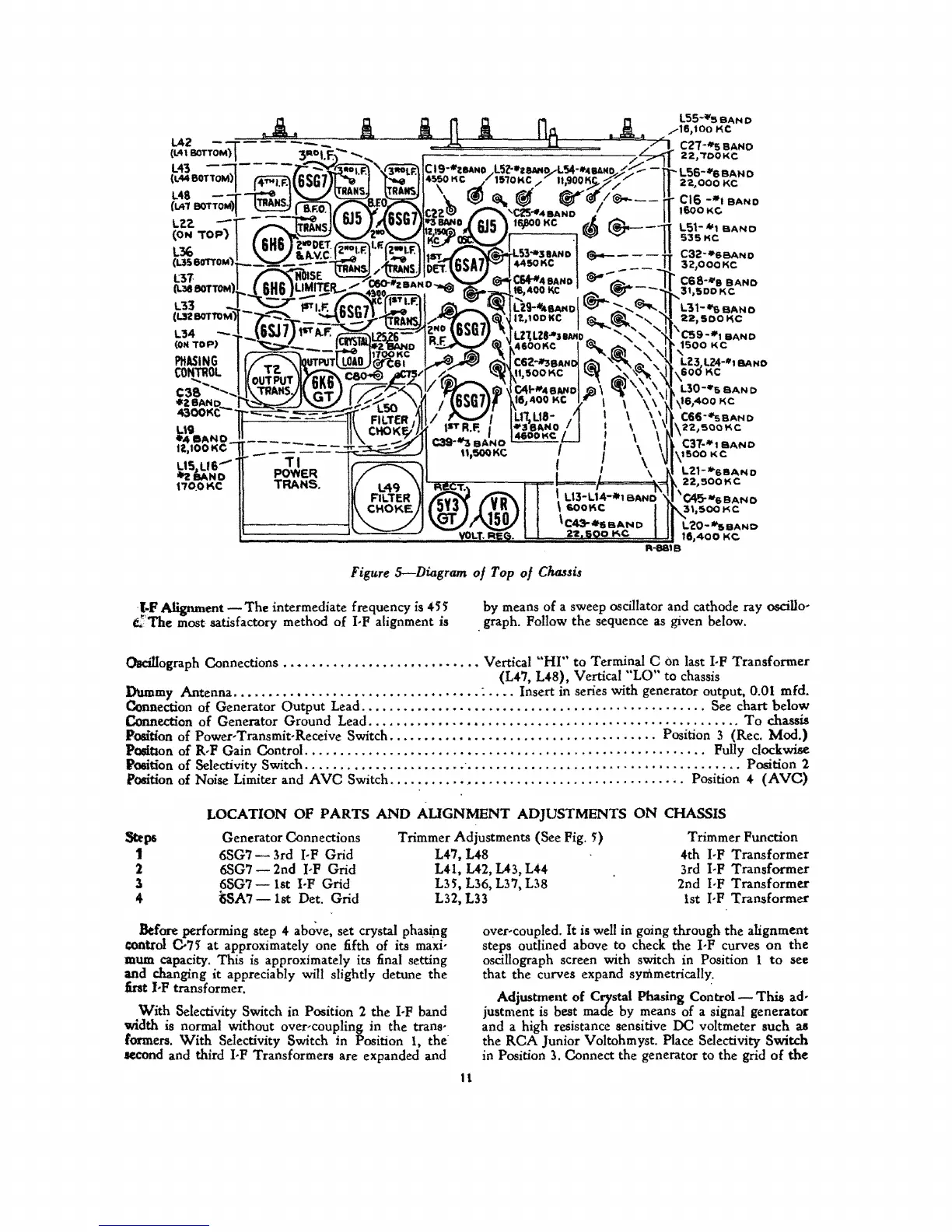
Figure
S-Diagram
of
Top
of
Cluusis
t.F Alignment -
The
intermediate frequency
is
4H
e:The most satisfactory method
of
I· P alignment is
by means of a sweep oscillator and cathode ray
oscillo;
graph. Pollow the sequence
as
given below.
Oaci1Iograph
Connections
..•....................•...•
Vertical
"HI"
to
Terminal C on last I·P Transformer
(L47,
L48), Vertical
"LO"
to chassis
Dummy Antenna
...................................
:
..•.
Insert in series with generator output. 0.01 mfd.
Connection of Generator Output Lead
............••.......•....•....................
" See chart below
Connection
of
Generator Ground Lead
......•.•....•••............•........................
To
chassis
Position of Power·Transmit·Receive Switch
..........•...........................
Position 3 (Rec.
Mod.)
PO$i.Uon
of
R·P Gain Control. . . . . . . . . . . . . . . . . . . . . . . • . . . . . . . . . . . . . . . . . . . . . . . . . . . . . . .
..
Pully clockwise
l1'oeition
of
Selectivity Switch
.........•............•
'
.......................................
Position 2
Position of Noise Limiter and A
VC
Switch
..........
'"
...........................
" Position 4
(AVe)
LOCATION
OF
PARTS
AND
AUGNMENT
ADJUSTMENTS
ON
CHASSIS
Step'
1
Generator Connections
6SG7-lrd
I·P Grid
6SG7 - 2nd
I,P Grid
Trimmer Adjustments
(See Pig.
S')
L47, L48
Trimmer
Punction
4th I·P
Transformer
3rd
I·P Transformer
2nd
I,P Transformer
2
1
4
6SG7 1st I·P Grid
MA7
-1st
Det. Grid
L41,
U2,
U3,
L44
US',
L36,
U7.
U8
L32,
L33
1st I,P Transformer
Before
performing step 4 abo've. set crystal phasi,ng
control
C7S' at approximately one fifth of its maxi·
mum
capacity. This
is
approximately its final setting
and changing it appreciably will slightly detune the
first
I-P transformer.
With
Selectivity Switch in Position 2 the I·P band
width
is
normal without over,coupling in the trans'
formers.
With
Selectivity Switch in Position I, the
second and third I· P Transformers are expanded and
n
over-coupled.
It
is
well
in going through the alignment
steps outlined above to check the I,P curves
on
the
oscillograph screen with switch in Position 1
to
see
that the curves expand symmetrically.
Adjustment of
Crystal Phasing
Control-
This
ad-
justment
is
best made by means of a signal generator
and a high resistance sensitive DC voltmeter such
as
the
RCA
Junior Voltohmyst. Place Selectivity Switch
in Position
3.
Connect the generator to the grid
of
the