6SA7 first det., and the Voltmeter to Terminal C
on
last I,F transformer (L47, L48). Tune the generator
to
about 7
k.c.
off
I,F resonance
and
adjust the crystal
phasing control
C7S
for minimum response.
Adjustment
of
Crystal Load Circuit - Make con'
nections
as
for the preceding adjustment.
(a)
Place Selectivity switch in Position
3.
Rock
the
signal generator frequency back and forth
across the
I,F resonant frequency and adjust
the crystal load circuit trimmer
L3'1
for sym'
metrical round,top curve.
(b)
Place the Selectivity switch in Position
4.
Rock
the
signal generator frequency and adjust trim-
mer
C81
for symmetrical curve.
(c)
Place the Selectivity switch in Position
5.
Ad,
just trimmer C80 rocking
the
signal generator
as for (a) and
(b)
above.
The
above three adjustments are very critical and
must be made carefully to obtain symmetrical curves.
Adjustment
of
Wave
Trap
- A wave trap is con-
nected across the broadcast band antenna primary
to
increase the rejection of I·P signal frequencies.
With
the
range switch on Position I, apply a modulated
I·F
signal to
the
antenna and ground terminals. Adjust
the wave trap trimmer
U7
(See Fig. 3) for minimum
output.
The
wave trap should
be
adjusted before
the
final
R-
F alignment on No. 1 band, or the antenna
coil alignment may be affected.
R·F Alignment - A signal generator covering a
range from
53
5 k.c.
to
32
megacycles, and an
output
voltmeter, are required.
It
is
desirable
to
connect a
speaker across the output terminals.
The
output volt-
meter should then
be
connected across the speaker
voice coil.
The
output impedance
is
2.25 ohms. Re·
move the cover from over the R·F unit by loosening
the four knurled screws and lifting
off.
Output
Meter Connections
......................................
,
............
Across speaker voice coil
Dummy Antenna
...................................................................
See chart below
Generator Modulation. . . . . . . . . . . . . . . . . . . . . . . . . • . . . • . . . . . . . . . . . . . . . . . . . . . . . . . . . . .
..
30% at 400 cycles
Position
of
Tone
Control.
........................
" . . ... . . . . . . . . . . . . . . . . . . . . . . . . . . . .
..
Fully clockwise
Position
of
Antenna Trimmer. . . . . . . . . . . . . . . . . . • . • . . . . . . . . . . . . . . . . . . . . . . . . . . . . . . .
..
.
..
See chart below
Position
of
Power-Transmit-Receive Switch
..........•...........................•
Position 3 (Rec. Mod.)
Position
of
Range Switch.. . . . . . . . . . . . . . . . . . . . . . . • . • . . . . . . . . . . . . . . . . . . . . . . . . . . . . . . .
..
See chart below
Position
of
R·P Gain Control. . . . . . . . . . . . . . . . . . . . . . . . . . . . . . . . . . . . . . . . . . . . . . . . . . . . . . .
..
Fully clockwise.
Position
of
Audio Gain Control. . . . . . . . . . . . . . . . . . . . . . . . . . . . . . . . . . . . . . . . . . . . . . . . . . . . .
..
Fully clockwise
Position
of
Noise Limiter and
AVC
Switch
..........................
<
................
Position 4
(A
VC)
Position
of
Selectivity Switch. . . . . . . . . . . . . . . . . . . . . . . . . . . . . . . . . . . . . . . . . . . . . . . . . . . • . . . • . . . .
..
Position 2
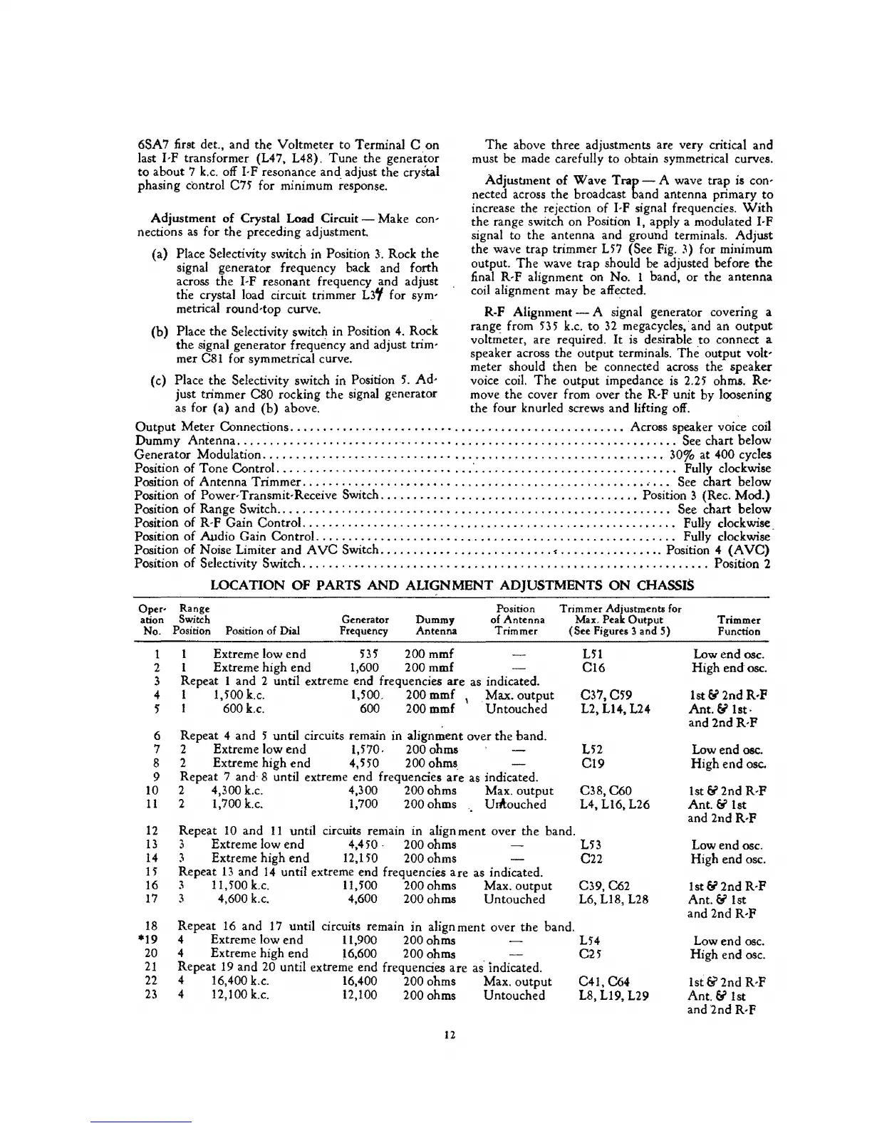
LOCATION
OF
PARTS
AND
ALIGNMENT
ADJUSTMENTS
ON
CHASSIS
Oper- Range
anon Switch
No. Position Position
of
Dial
Generator
Frequency
Dummy
Antenna
1 Extreme low end
53
5 200 mmf
2 Extreme high end
1,600 200 mmf
Position
of Antenna
Trimmer
3 Repeat 1 and 2 until extreme end frequencies
are
as indicated.
4 1
1,500 k.c. 1,500, 200 mmf \ Max.
output
5 I 600 k.c. 600 200 mmf Untouched
6 Repeat 4 and
5 until circuits remain in alignment over the band.
7 2 Extreme low end
1,570. 200 ohms
8 2 Extreme high end
4,550 200
ohms.
9 Repeat 7 and- 8 until extreme end frequencies
are
as indicated.
10 2 4,300 k.c. 4,300 200 ohms Max. output
11
2 1,700 k.c. 1,700 200 ohms UIA:ouched
Trimmer Adjustments for
Max. Peak
Output
(See Figures 3 and S)
L51
C16
C37.C59
L2.
Ll4,
L24
152
C19
C38,C60
L4,
Ll6,
L26
12
Repeat
10
and
11
until circuits remain in alignment over the band.
13
3 Extreme low end 4,450 . 200 ohms L53
14
3 Extreme high end 12,150 200 ohms C22
15
Repeat
13
and
14
until extreme end frequencies
are
as indicated.
16
3 11,500 k.c. 11,500 200 ohms Max. output C39, C62
17
3 4,600
k.c.
4,600 200 ohms Untouched L6,
Ll8,
L28
18
Repeat
16
and
17
until circuits remain in align ment over the band.
*19 4 Extreme low end
11,900 200 ohms
L54
20
4 Extreme high end 16,600 200 ohms
CH
21
Repeat
19
and 20 until extreme end frequencies are as indicated.
22
4 16,400 k.c. 16,400 200 ohms Max. output C41, C64
23
4 12,100
k.c.
12,100 200 ohms Untouched L8, L19, L29
12
Trimmer
Function
Low end osc.
High
end
osc.
lst&
2ndR,P
Ant. &
Ist·
and
2ndR-P
Low end
osc.
High
end
~sc.
1st
&2nd
R-P
Ant. & 1st
and 2nd
R-P
Low end osc.
High end osc.
1st
& 2nd R-P
Ant. & 1st
and 2nd
R-P
Low end
osc.
High end osc.
Ist&2nd
R-P
Ant. & 1st
and
2nd
R·F