Halt Device
(HDV)
General
Description
Format
(SI)
Condition Code
Interrupt
Action
Notes
Privileged
In8tructions
• The contents of the general register specified
by
Bl
are
added to
the
Dl
field,
and
the
resultant sum identifies
the
channel
to
be halted. The channel
is specified by
bit
positions
21
through
23
of
the
sum.
If
a multiplexor is
specified,
bit
positions 24 through
31
of
the
sum identify the device to be
halted. The I field is not used and
must
be zeros. Bufferred devices operating
off-line, and independent of
the
channel/device control electronics, cannot
be stopped by using this instruction. The condition code specifies
the
results
of
the
instruction.
9E
o
7 8
15 16 19
20
31
• 0
-not
busy.
1-
standard
device byte stored in scratch-pad memory.
2 - termination accepted.
3 - inoperable.
(For
a detailed description of
the
condition code settings, see Notes
below.)
• Privileged operation.
•
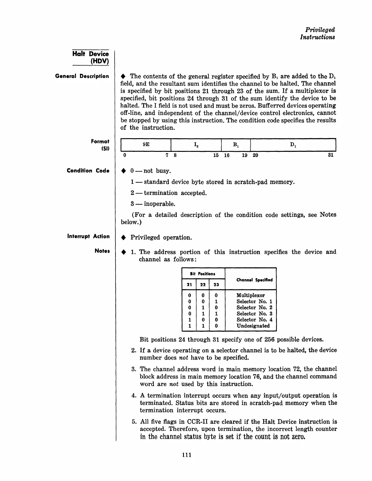
1.
The address portion
of
this
instruction specifies
the
device and
channel as follows:
Bit
Positions
Chann.1
Specified
21
22
23
0 0 0
Multiplexor
0 0 1 Selector No. 1
0 1 0 Selector
No.2
0 1
1 Selector No. 3
1 0
0
Selector No. 4
1 1 0
Undesignated
Bit
positions 24 through
31
specify one
of
256 possible devices.
2.
If
a device operating on a selector channel is to be halted,
the
device
number does
not have to be specified.
3.
The channel address word in main memory location 72, the channel
block address in main memory location 76, and the channel command
word
are
not used by this instruction.
4.
A termination
interrupt
occurs when any
input/output
operation is
terminated.
Status bits
are
stored
in
scratch-pad memory when the
termination
interrupt
occurs.
5.
All
five
flags in CCR-II
are
cleared
if
the
Halt
Device instruction is
accepted. Therefore, upon termination, the incorrect length counter
in
the
channel
status
byte
is
set
if
the
count
is
not
zero.
111
 Loading...