Program
Mask
Registers
(Cont'd)
Register
Addressing
Interrupt Flag Register
Program Interrupt
The
program
mask
bit
settings have
priority
over
the
bit
settings in
the
Interrupt
Mask register
for
the above
four
program
interrupts.
A 0
bit
in
any
bit
position in
this
register
cancels the
interrupt
condition
if
it
occurs. A 1
bit
in
any
bit
position in
this
register
indicates
that
the
Inter-
rupt
Mask
register
is to be examined.
If
an
interrupt
condition occurs
and
is inhibited by the
Interrupt
Mask register,
it
remains pending until
it
is
serviced (permitted) .
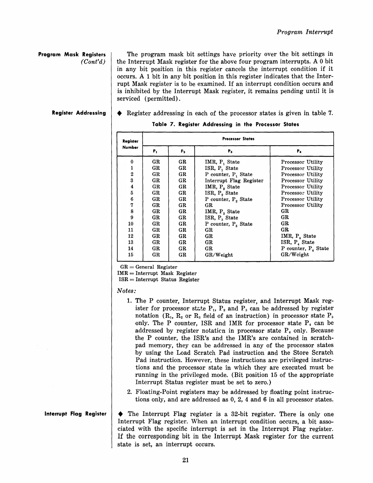
• Register addressing in each of
the
processor
states
is given in table
7.
Table 7. Register Addressing
in
the
Processor States
Register
Number
PI
F2
0
GR
GR
1
GR
GR
2
GR
GR
3 GR
GR
4
GR GR
5 GR
GR
6
GR GR
7
GR GR
8
GR GR
9
GR
GR
10
GR
GR
11
GR
GR
12
GR
GR
13
GR
GR
14
GR
GR
15
GR
GR
G R = General
Register
IMR =
Interrupt
Mask
Register
ISR
=
Interrupt
Status
Register
Notes:
Processor States
P
3
P4
IMR, P
l
State
Processor
Utility
ISR, P
l
State
Processor
Utility
P counter, P
l
State
Processor
Utility
Interrupt
Flag
Register Processor
Utility
IMR, P 2
State
Processor
Utility
ISR, P 2
State
Processor
Utility
P counter, P 2
State
Processor
Utility
GR
Processor
Utility
IMR, P 3
State
GR
ISR, P 3
State
GR
P counter, P 3
State
GR
GR
GR
GR
IMR, P 4
State
GR
ISR, P 4
State
GR
P counter, P
4
State
GR/Weight
GR/Weight
1. The P counter,
Interrupt
Status
register,
and
Interrupt
Mask reg-
ister
for
processor stc.te P
11
P 2
and
P 3 can be addressed by
register
notation
(R
1
,
R2
or
R3
field
of
an
instruction) in processor
state
P
3
only. The P
counter, ISR and IMR
for
processor
state
P 4 can be
addressed by
register
notaticn in processor
state
P 4 only. Because
the P counter,
the
ISR's
and
the
IMR's
are
contained in scratch-
pad memory, they can be addressed in
any
of
the
processor
states
by using the Load Scratch
Pad
instruction
and
the
Store
Scratch
Pad
instruction. However, these instructions
are
privileged instruc-
tions
and
the processor
state
in which they
are
executed
must
be
running
in the privileged mode.
(Bit
position 15 of
the
appropriate
Interrupt
Status
register
must
be set to zero.)
2.
Floating-Point registers may be addressed by floating point instruc-
tions only,
and
are
addressed as
0,
2,
4
and
6 in all processor
states
.
• The
Interrupt
Flag
register is a 32-bit register.
There
is only one
Interrupt
Flag
register. When
an
interrupt
condition occurs, a
bit
asso-
ciated
with
the
specific
interrupt
is set in
the
Interrupt
Flag
register.
If
the corresponding bit in the Interrupt Mask register for the current
state
is set,
an
interrupt
occurs.
21