13
ENGLISH
RCF S.p.A. would like to thank you for having purchased this product, which
has been designed to guarantee reliability and high performance.
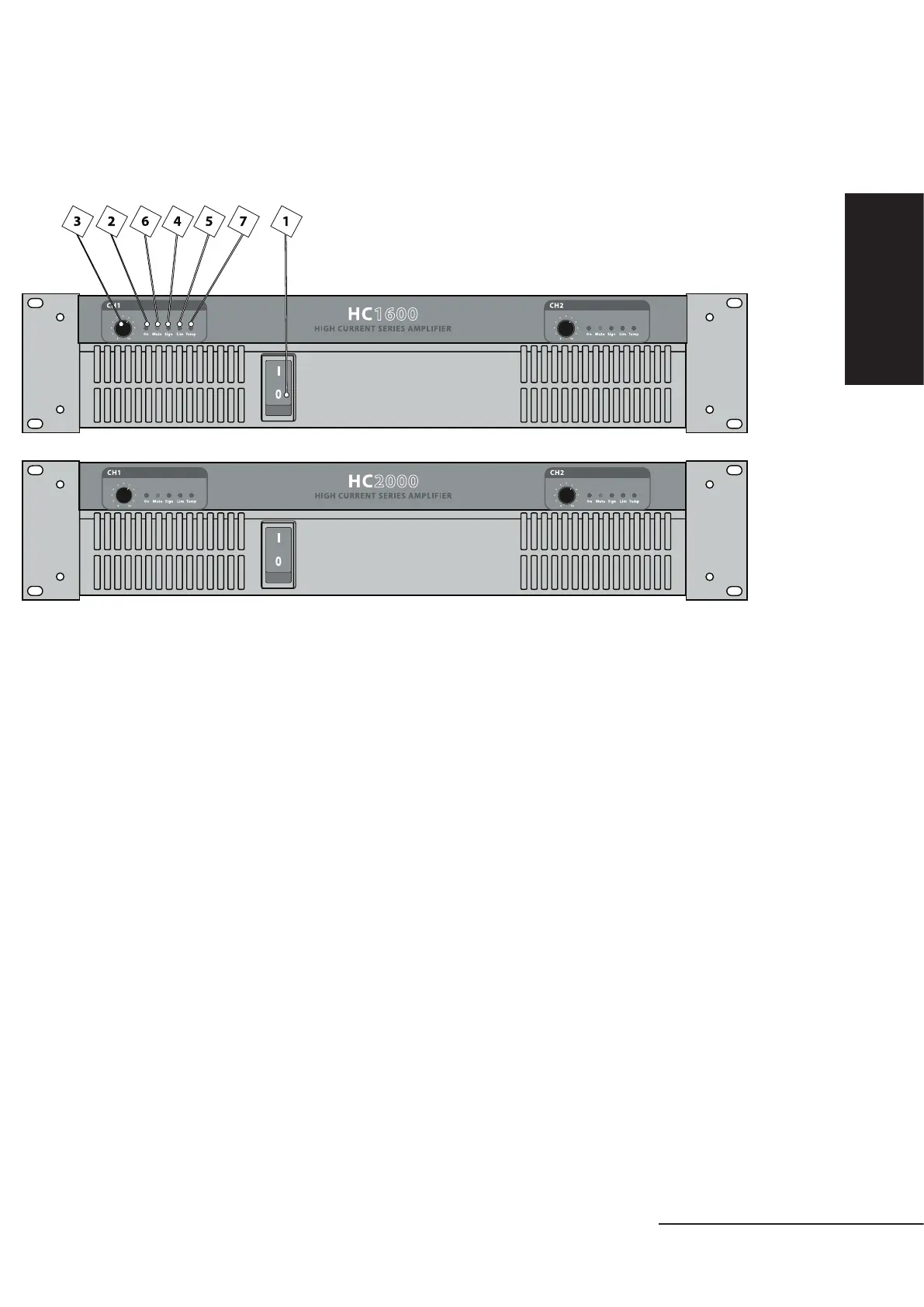
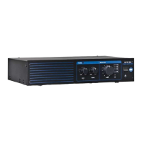
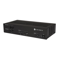
FRONT PANEL
1. MASTER SWITCH
It switches the amplifier on / off (interrupting both the phases).
2. POWER ON INDICATOR
Green LED indicating the correct channel operation.
3. VOLUME CONTROL
Control to adjust the channel volume level.
Note: in MONO and BRIDGE modes, use the control CH1 only.
4. SIGNAL (-20 dB) INDICATOR
Green LED indicating the signal presence in the final stages of the respective channel
(at a level of at least -20dB).
5. LIMITER - PEAK INDICATOR
Red LED indicating the maximum amplification level (peak) has been reached and the consequent
internal limiter activation in the respective channel.
If it stays lit continuously, the input signal is excessive.
6. MUTE INDICATOR
Yellow LED indicating the mute status of the channel due to one (or more) of the following reasons:
• Switch-on delay (3 seconds).
• Direct voltage on the channel output.
• Short circuit.
• Channel thermal protection.
• Transformer thermal protection.
7. THERMAL PROTECTION INDICATOR
Red LED indicating a too high temperature. When the protection function is triggered, the
amplifier remains in the mute status until the normal operating temperature is restored. The
thermal protection indicates an overheating of a channel and / or the transformer (in this second
case, both the 2 red LEDs, ch.1 and ch.2, stay lit).