-40
+4
-38
-36
-34
-32
-30
-28
-26
-24
-22
-20
-18
-16
-14
-12
-10
-8
-6
-4
-2
+0
+2
d
B
u
20 20k50 100 200 500 1k 2k 5k 10k
Hz
T
47
Under the above conditions air absorption at 10KHz can reach 0.3dB/m at 20% RH. This means 30dB excess
attenuation (over and above the 3dB per doubling of distance) at 100m from the column. The incredible high
frequency efficiency and headroom of the TTL33-A can prove beneficial here. Air absorption also varies with
temperature and is notoriously difficult to predict with accuracy.
The best policy is to get your crew to check all audience areas during the performance and apply a sensible
amount of correction. Luckily, a large audience tends to raise the local humidity so HF absorption often reduces
once the audience is in place. Line array systems should be corrected with caution and distant audience areas
rechecked at regular intervals during large events.
HIGH-FREQUENCY COUPLING EFFECTS
Planning for high-frequency coverage is a matter of deciding the number of elements and fine-tuning the splay angles
between cabinets. The number of elements does not necessarily have a significant impact on SPL at high frequencies
(it will at low frequencies), but can profoundly affect vertical coverage and throw capabilities of the array.
For the far field, a smaller mechanical splay angle between cabinets achieves superior throw through better coupling
to compensate for energy lost over distance. The longer the throw needed, the more elements needed with smaller
angles at the top of the array. In the near- to mid-field, larger splay angles are used to increase vertical coverage.
LOW-FREQUENCY COUPLING EFFECTS
While wave-guides provide isolated control over various mid- to high-frequency coverage areas, the low-frequency
section of a TTL33A array still requires mutual coupling - with equal amplitude and phase - to achieve better
directionality.
Low-frequency directionality is less dependent on the array’s relative splay angles and more dependent on the
number of elements of the array.
At low frequencies, the more elements in the array (the longer the array), the more directional the array becomes,
providing more SPL in this range. The directional control of the array is achieved when the length of the array is
similar or larger than the wavelength of the frequencies being reproduced by the array.
OPTIMIZING THE ARRAY
Once the design (number of elements and vertical splay angles) has been designed using SHAPE DESIGNER software,
you can effectively optimize the array depending on the environment and the application by driving it using different DSP
presets stored onboard. Typically arrays are divided in two or three zones depending the design and size of the array.
To optimize and EQ the array, different strategies are used for high frequencies (long throws and short throws) and low frequencies.
HIGH-FREQUENCY EQUALIZATION STRATEGIES
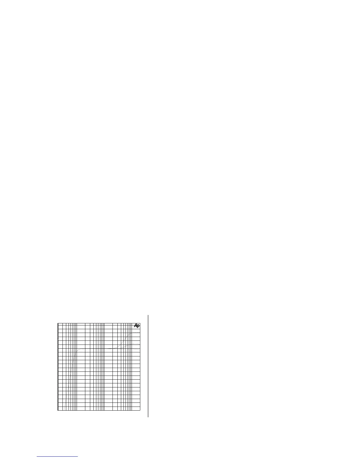
For the far field, air absorption plays a critical role. The longer
the distance, the greater the attenuation at high frequencies.
In this zone, high frequencies generally need a correction to
compensate for energy lost over distance; the correction needed
is usually proportional to the distance and high-frequency air
absorption. In the near- to mid-field, the air absorption is not
nearly as critical; in this zone, high frequencies need little or no
additional correction.
In the next figure is shown the equalization that corresponds to
DSP settings for “near field”, “mid field” and “far field”: