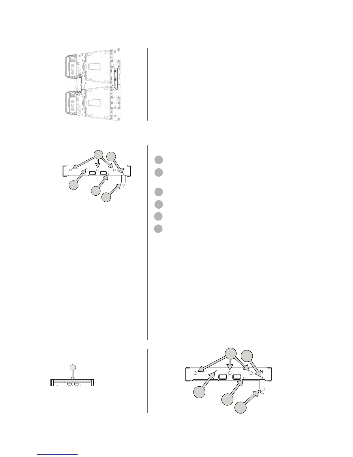
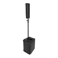
THE TTL55-A FLY BAR
The TTL55-A system must be suspended
using the RCF TTL55-A fly bar
THE TTL55-A FLY BAR FEATURES:
1 FRONT FLYING BRACKET
2 QUICK LOCK PIN HOLE (to be used to lock
the front bracket before installation)
3 REAR BAR HOLE
4 SAFETY CHAIN SHACKLE HOLES
5 QUICK LOCK PIN HOLE
6 PICKUP FIXING HOLES
2
3
4
5
1
2
3
4
5
1
6
17
The TT+ line arrays module is provided with 4 rigging bars, 2 in
the front and 2 in the rear corners. The rigging bars are securely
connected to front and rear metal corners. Front and rear metal
corners are securely connected to the cabinet. The rigging system is
made of rigging bars and metal corners in sequence. Rigging bars
and metal corners are securely connected by:
- Rectified bolts
- Quick lock pins The wooden cabinet is not a primary part of the
rigging system.
RIGGING SYSTEM