14
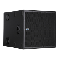
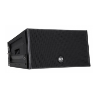
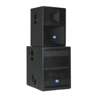
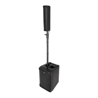
TTL33-A/TTL31-A
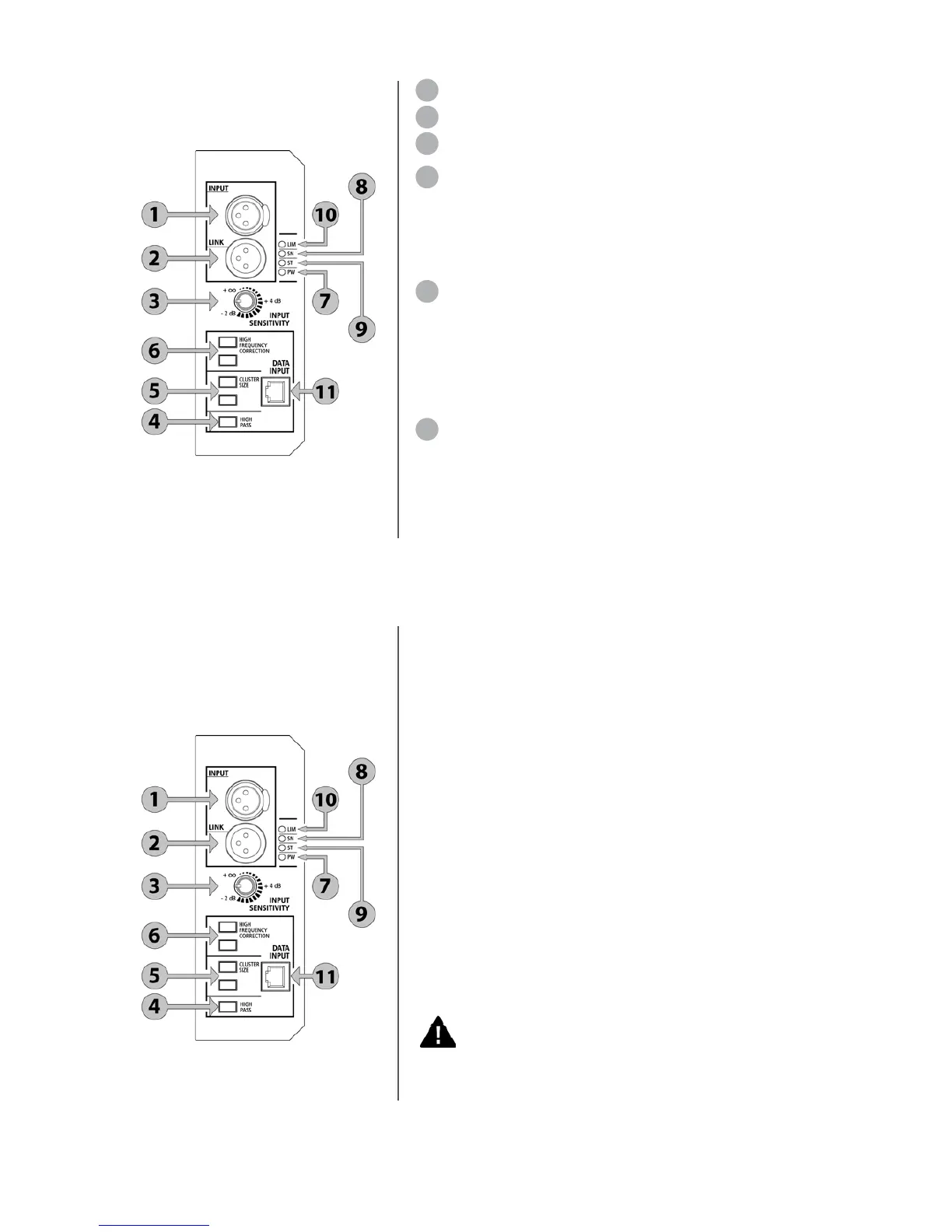
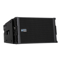
INPUT PANEL
1 XLR INPUT.
2 XLR LINK OUTPUT.
3 SENSITIVITY ( +
∞
, +4 dB, -2 dB).
4 HIGH PASS.
This switch inserts a 110 Hz, 24 dB/octave high pass,
to be used in conjunction with subwoofers without any high pass signal
output. When the system is used in conjunction with the TTS18-A or
TTS28-A subwoofers the optimum solution is to use the high pass xover
signal output from the subs and leave the line array module in full range.
5 CLUSTER SIZE. The combination of the 2 central switches gives 4
possibilities of mid low frequencies correction depending on cluster size:
• 2-3 modules (used for stacking configurations)
• 4-6 modules (small flown systems)
• 7-9 modules (medium flown systems)
• 10-16 modules (large flown systems)
6 HIGH FREQUENCY CORRECTION. The combination of the 2
top switches gives 3 possibilities of high frequencies correction
depending on target distance (air absorption correction):
-near field ( up to 30 meters)
-mid field ( from 30 to 60 meters)
-far field ( more than 60 meters)
7 GREEN - POWER LED. This led is ON when the system is connected
to the AC power source and the main on/off switch is in position 1.
8 GREEN - SIGNAL LED. This led is ON when the audio input signal
is superior to -20 dB. When there is no input signal the led is flashing.
9 YELLOW - STATUS LED. This LED is flashing during the bootstrap
procedure and in case of communication problems with the DSP processor.
10 RED/ORANGE - LIMITER LED. This led is ON when the limiter
circuit is active to prevent output distortion or damage of the speaker:
ORANGE - Soft limiter circuit. When the LED is flashing ORANGE
one of the power amplifiers reaches the maximum output for short
periods of time and the working condition can be considered normal.
RED - Hard limiter. When the LED is flashing RED (following the
signal) one of the power amplifiers reaches the maximum output
for longer periods of time. When the LED is blinking RED one of the
RMS limiter circuit is active in order to prevent damage to one of the
transducers or power amplifiers.
Always avoid operating conditions where the System works for
long periods of time with the RED LED flashing or blinking.
11 DATA INPUT. This port is used to update DSP firmware, DSP
presets, microprocessor firmware.
TTL33-A/TTL31-A
INPUT PANEL LEDS
The input panel presents 4 system LEDs: