11
4.
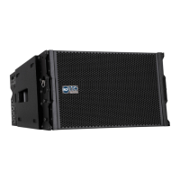
THE TTL SYSTEM
AUDIO CONNECTIONS AND CABLING
The TTL33-A/TTL31-A input panel presents balanced XLR input/output.
SIGNAL CABLES DAISY CHAINS
Audio signal can be daisy-chained using the male XLR loop through connectors. A single audio source can drive multiple
speakers modules (like a full left or right channel made of 8-16 speaker modules); make sure that the source device is
able to drive the impedance load made of the modules input circuits in parallel.
The TTL33-A/TTL31-A input circuit presents a 100 KOhm input impedance. The total input impedance seen as a load
from the audio source (ex. audio mixer) will be:
• system input impedance = 100 KOhm / number of input circuits in parallel.
The required output impedance of the audio source (ex. audio mixer) will be:
• source output impedance > 10 * system input impedance
• always make sure that XLR cables used to feed audio signal to the system are:
- balanced audio cables
- wired in phase
A single defective cable can affect the performance of the overall system!
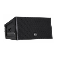
TTL33-A/TTL31-A
INPUT PANEL
1 XLR INPUT.
2 XLR LINK OUTPUT.
3 SENSITIVITY ( +
∞
, +4 dB, -2 dB).
4 HIGH PASS.
This switch inserts a 110 Hz, 24 dB/octave high pass,
to be used in conjunction with subwoofers without any high pass signal
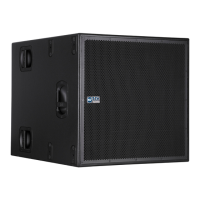
output. When the system is used in conjunction with the TTS18-A or
TTS28-A subwoofers the optimum solution is to use the high pass xover
signal output from the subs and leave the line array module in full range.
5 CLUSTER SIZE. The combination of the 2 central switches gives 4
possibilities of mid low frequencies correction depending on cluster size:
• 2-3 modules (used for stacking confi gurations)
• 4-6 modules (small fl own systems)
• 7-9 modules (medium fl own systems)
• 10-16 modules (large fl own systems)
6 HIGH FREQUENCY CORRECTION. The combination of the 2
top switches gives 3 possibilities of high frequencies correction
depending on target distance (air absorption correction):
-near fi eld ( up to 30 meters)
-mid fi eld ( from 30 to 60 meters)
-far fi eld ( more than 60 meters)
 Loading...