15
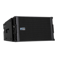
The TTL33-A/TTL31-A module is provided with 4 rigging bars, 2 in
the front and 2 in the rear corners. The rigging bars are securely
connected
to front and rear metal corners. Front and rear metal corners are
securely connected to the cabinet. The rigging system is made of
rigging bars and metal corners in sequence. Rigging bars and metal
corners are securely connected by:
- M10 rectifi ed bolts
- Quick lock pins The wooden cabinet is not a primary part of the
rigging system.
RIGGING SYSTEM
THE TTL33-A FLY BAR
The TTL33-A system must be suspended
using the RCF TTL33-A fl y bar
THE TTL33-A FLY BAR FEATURES:
1 FRONT FLYING BRACKET - Front mounting
2 QUICK LOCK PIN HOLE - Front mounting (to be used to lock
the front bracket before installation)
3 REAR BAR HOLE - Front mounting
4 FRONT FLYING BRACKET - Rear mounting
5 QUICK LOCK PIN HOLE - Rear mounting (to be used to lock
the front bracket before installation)
6 REAR BAR HOLE - REAR MOUNTING.
7 FRONT STACKING POINT.
8 REAR STACKING POINT - UPPER POSITION.
9 REAR STACKING POINT - LOWER POSITION.
10 FRONT BRACKET - TRANSPORT POSITION HOLE.
11 REAR BRACKET - TRANSPORT POSITION HOLE.
12 CORNER DOUBLE-MOTOR PICK-UP POINT.
13 CORNER DOUBLE-MOTOR PICK-UP POINT.
14 12 CENTRAL PICK-UP POINTS.
10
 Loading...