DCN: 141-01060-13 1/05 TS40 Manual
22
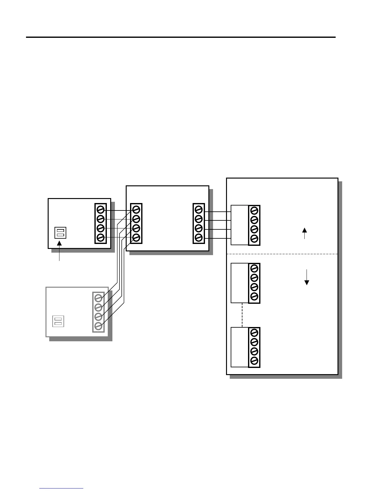
TS40 Wiring Diagram
Wiring Instructions
• Remove power from control unit.
• Connect the WDU to the Thermostat Control Unit (TS40).
• For Zone Controllers, connect each zone’s WDU to its respective zone input.
• Connect optional Remote Sensors to the Wall Display Unit’s remote sensor input. See Remote
Sensor wiring information for sensor address setting.
• Double check wiring before applying power to control unit.
RCS
TS40
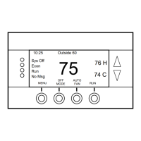
Wall Display Unit
+
C
D
12V
GND
D
C
TR40 Thermostat or
ZCV2/4/6 Zone Controllers
C
RS
+
C
D
Optional
RS15
Remote Sensor
Remote Sensor
Control Unit
HVAC Control Unit
12V
GND
D
C
Wall Display Units
12V
GND
D
C
Zone 1
Zone 2
Zone 6
Thermostats have
only one WDU
Zone Controllers can
have up to 6 WDU’s
CAUTION!
Check wiring before applying power.
Mis-wiring the WDU to Control unit
connections may result in damage.
+
C
D
ddress
Remote Sensor Address
must be set for correct
sensor operation
+
C
D
ddress
dditional Remote Sensors wire in parallel
to the WDU remote sensor connector.